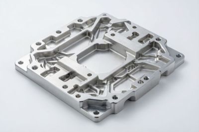
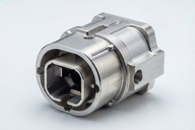
5-Axis CNC Machining for Drone Gimbal Frames and Motor Mounts
A gimbal is only as stable as the frame holding it. The moment a drone leaves the ground, every gram of mass and every micron of misalignment shows up as jitter in the footage or drift in the targeting sensor. That is why the teams we work with - from a survey-drone startup whose first production order with us reached 1.2 million RMB to established industrial UAV makers - treat the gimbal frame and motor mounts as flight-critical parts, not cosmetic housings.
In this guide we walk through how 5-axis CNC machining earns its place in UAV structural components, where lightweight CNC machining actually pays off, and how material choice between TC4 titanium and aerospace-grade aluminum changes your stiffness-to-weight math. We will also cover the tolerances and surface finishes that keep optics steady, plus a sourcing checklist you can hand to a supplier today.
We have been a Dongguan source factory for precision CNC work since 2015, with 60 machines, a 2,000 sqm floor, and monthly output around 500k parts. This is written from the shop floor, not a catalog - the numbers and trade-offs are the ones we argue about with customers before a single chip is cut.
Table of Contents
- 1. Why 5-Axis CNC Machining Wins for Drone Gimbal Frames
- 2. Designing Drone Motor Mounts That Survive Vibration
- 3. UAV Structural Components: Where Weight Savings Matter Most
- 4. Lightweight CNC Machining: Aluminum vs Titanium Trade-offs
- 5. TC4 Titanium Machining for Gimbal Arms and Housings
- 6. Choosing Aerospace-Grade Aluminum for UAV Frames
- 7. 5-Axis CNC Machining Tolerances That Keep the Optics Steady
- 8. A Practical Sourcing Checklist for UAV Structural Components
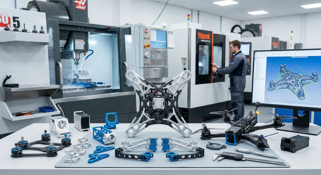
UAV/Drone: drone
Why 5-Axis CNC Machining Wins for Drone Gimbal Frames
One setup, three faces, zero datum-shift - that is the whole game.
A gimbal frame is a thin-walled, multi-angle part: bolt bosses on one face, a cradle on another, wire-routing ribs on a third. Cutting it on a 3-axis machine means re-fixturing two or three times. Every re-clamp is a chance to introduce a datum shift of 0.02 to 0.05 mm, and on a part this size that is the difference between buttery stabilization and a visible wobble.
5-axis CNC machining cuts those features in a single setup, holding the part on one datum while the table and head rotate. We routinely hold positional accuracy to +/-0.005 mm across all three faces because the coordinate system never moves. For a customer building a 3-axis stabilized payload, that single-setup consistency is what lets them skip the hand-lapping step they used to do after machining.
Where 3-axis still makes sense
Not every UAV structural component needs five axes. Flat motor plates, simple brackets, and high-volume spacers are cheaper and faster on 3+1 or even 2.5-axis work. The rule we give customers: if a part has more than two angled feature groups that must stay mutually true, go 5-axis; otherwise don't pay for it.
| Factor | 3-axis (multi-setup) | 5-axis (single setup) |
|---|---|---|
| Datum shifts | 0.02-0.05 mm per re-clamp | None after first clamp |
| Typical cycle | Longer (re-fixturing) | Shorter per part |
| Best for | Flat plates, brackets | Cradles, gimbals, arms |
| Our accuracy | +/-0.01 mm | +/-0.005 mm |
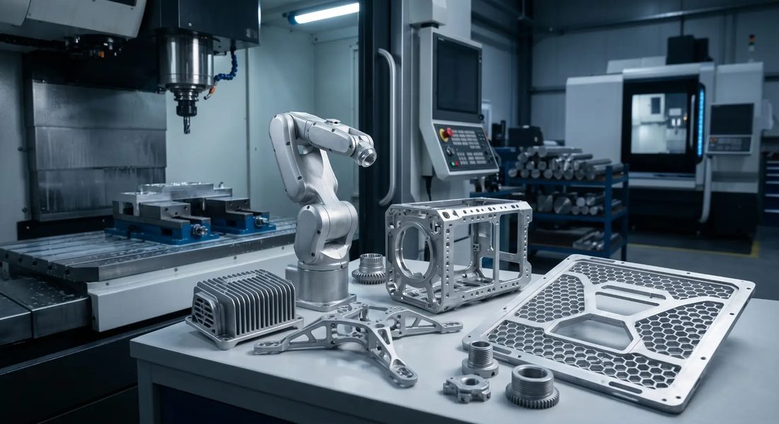
UAV/Drone: aircraft
Designing Drone Motor Mounts That Survive Vibration
A motor mount fails quietly - until the rotor walks off.
Drone motor mounts live in a hostile place: continuous rotor vibration, thermal swings from -20 to 60 C, and the occasional hard landing. The failure mode is almost never a clean break; it is fretting at the bolt circle that lets the motor tilt a fraction of a degree, which the flight controller compensates for until it can't.
We design mounts around three principles. First, keep the bolt pattern symmetric so clamp load is even. Second, add a lightening pocket that raises the first resonant frequency above the rotor's operating band - typically above 400 Hz for a 5-inch prop. Third, specify a surface finish that lets thread-locker bite; we hold Ra 1.6 micro m on the seat face, and Ra 0.6 micro m or better where the motor pilot registers.
Bolt circle and pilot tolerances
- Pilot diameter: h7 fit to the motor boss
- Bolt circle true position: +/-0.03 mm
- Seat flatness: 0.02 mm over the face
- Corner radii: R0.5 min to avoid stress cracks
UAV Structural Components: Where Weight Savings Matter Most
Cut mass where it multiplies flight time - not everywhere.
Every gram removed from a UAV structural component near the gimbal or at the rotor tip buys more than a gram at the frame center. Payload and rotor-tip parts see the highest return on lightweighting because they change the inertia tensor the flight controller fights every millisecond.
We map mass-removal priorities with customers before machining: (1) gimbal yoke and cradle, (2) motor mount webs, (3) arm clamps, then (4) central plates. Trimming the central plate is last because it rarely changes handling and is easy to over-thin into a wobble.
- List every non-flight-critical volume on the CAD
- Simulate first-mode frequency after each pocket
- Keep wall thickness >= 0.8 mm in aluminum, >= 0.6 mm in titanium
- Verify the real part on a shake table before sign-off
| Location | Weighting priority | Typical save |
|---|---|---|
| Gimbal yoke/cradle | Highest | 8-12% of local mass |
| Motor mount webs | High | 10-15% of local mass |
| Arm clamps | Medium | 5-8% of local mass |
| Central plate | Lowest | 3-5% of local mass |
UAV/Drone: factory
Lightweight CNC Machining: Aluminum vs Titanium Trade-offs
Titanium is not 'better aluminum' - it is a different engineering deal.
Lightweight CNC machining is really a stiffness-per-gram optimization. Aerospace-grade aluminum (we mostly run 7075-T6 and 6061-T6) lands near 2.8 g/cc with a modulus around 71 GPa. TC4 titanium sits at 4.43 g/cc but a modulus near 114 GPa and roughly double the strength. So for a part limited by bending stiffness, titanium can be lighter even though it is denser, because you need less of it.
The catch is machinability and cost. Titanium work-hardens, runs hot, and eats tool life; cycle times run two to three times an equivalent aluminum part. Aluminum is cheaper, faster, and kinder to your tolerance budget. We steer customers to titanium only when strength-to-weight or corrosion resistance genuinely drives the design.
Pros
- Higher specific stiffness for bending-limited parts
- Excellent corrosion resistance, no coating needed
- Survives thermal cycles without creep
- Premium, defensible spec for aerospace buyers
Cons
- 2-3x cycle time vs aluminum
- Higher blank and tooling cost
- Tighter heat management at the cut
- Harder to hit very low Ra without extra pass
TC4 Titanium Machining for Gimbal Arms and Housings
Cool, sharp, and shallow - the three rules we machine titanium by.
TC4 titanium machining rewards discipline. The material conducts heat poorly, so the cut zone heats fast and work-hardens if you let the tool rub. Our recipe: low radial engagement (around 0.5 mm or 8 percent of the cutter diameter), sharp uncoated or AlTiN inserts, flood or through-spindle coolant, and conservative surface speeds near 30-50 m/min.
For gimbal arms we typically leave 0.1 mm for a finishing pass and hold the contour to +/-0.01 mm. Housings with thin walls get a tensioning fixture so they don't spring during the final cut, then we relax and measure the free-state form - that is the number the customer's assembly actually sees.
Finish and passivation
After machining we passivate per ASTM A967 so the surface resists fingerprint corrosion during handling, and we can take the visible faces to a brushed or bead-blasted finish. For parts that must look as good as they fly, our mirror line reaches Ra 0.2 micro m, though most UAV arms stop at Ra 0.8 micro m for function.
- Confirm material cert (ASTM B348 Grade 5 / TC4)
- Agree on coolant and passivation spec up front
- Define free-state vs clamped tolerances
- Plan fixture relief for thin walls
- Decide final Ra on visible faces
UAV/Drone: metal
Choosing Aerospace-Grade Aluminum for UAV Frames
7075 for stress, 6061 for everything else - most frames are 6061.
Aerospace-grade aluminum is the default for the majority of UAV structural components because it is cheap, stable, and easy to hold to tight tolerances. 6061-T6 covers most frames, clamps, and plates; 7075-T6 steps in where yield strength matters and you can manage its lower corrosion resistance with anodize.
We anodize most aluminum UAV parts - Type II for a durable matte black that hides handling marks, Type III hard coat where the surface sees abrasion. Anodize adds a few microns and can close a 0.005 mm slot, so we machine the bore undersize and let the coating bring it to nominal. Miss that and your press-fit motor suddenly won't seat.
| Alloy | Use it for | Watch out for |
|---|---|---|
| 6061-T6 | Frames, plates, clamps | Lower strength vs 7075 |
| 7075-T6 | High-stress arms, yokes | Corrosion; anodize required |
| 2024-T3 | Fatigue-critical skins | Poor corrosion, rare in UAV |
5-Axis CNC Machining Tolerances That Keep the Optics Steady
Tolerance is a budget - spend it where the image depends on it.
Stabilization quality is set by how true the optic seat is to the rotor axis. We concentrate the tolerance budget on three relationships: the lens-seat flatness, the seat-to-motor-axis perpendicularity, and the cradle's angular repeatability when it tilts. Everything else gets commercial tolerances to keep cost sane.
Concretely, we hold lens-seat flatness to 0.01 mm, perpendicularity of the seat to the motor pilot at 0.02 mm, and we inspect the first article on a CMM with a full datum report. Batch parts get in-process gauging and lot-level CMM audits so a drift in the process shows up before a bad lot ships.
- Spend tight tolerance on optic seat and motor pilot
- Relax non-functional faces to commercial
- CMM first article, gauge in-process
- Lot traceability from raw bar to finished part
UAV/Drone: circuit,board
A Practical Sourcing Checklist for UAV Structural Components
Hand this to a supplier and you will filter out the tire-kickers.
Sourcing UAV structural components is less about finding a cheap machine and more about finding a shop that understands flight-critical intent. The questions below are the ones we are happy to answer with data, and the ones that separate a real precision source from a broker with a logo.
- Ask for the cert stack: ISO 9001 minimum, AS9100 or IATF 16949 a plus
- Request material certs traceable to the heat lot
- Confirm single-setup 5-axis capability, not 3-axis with re-fixturing
- Get a CMM first-article report, not just a photo
- Agree on coated vs bare tolerances before quoting
- Verify batch traceability and a real rework path
The cheapest gimbal frame is the one that passes qualification the first time - because the second time costs you a launch date.
UAV/Drone: robotic,arm
UAV/Drone: warehouse
UAV/Drone: machining
UAV/Drone: propeller
FAQ: 5-axis CNC machining & UAV/Drone Buyer Questions
A: Yes, on a single setup. The key is never releasing the datum; with the part clamped once and the axes rotating, we hold positional accuracy to +/-0.005 mm across all faces. Thin walls need a tensioning fixture so the part doesn't spring during the finishing pass.
A: Only when stiffness-to-weight or corrosion resistance drives the design. Titanium's higher modulus lets you use less material for a bending-limited part, but cycle time runs 2-3x aluminum. For most frames 6061 or 7075 aluminum is the better value.
A: We machine the bore undersize by the anticipated coating thickness - typically a few microns for Type II, more for Type III hard coat - so the finished, coated bore lands at nominal. Designing to the bare condition is the classic mistake that causes binding.
A: Hold Ra 1.6 micro m on the seat face so thread-locker grips, and Ra 0.6 micro m or better on the motor pilot registration. The cradle and optic seat can go finer, down to our mirror-ready Ra 0.2 micro m when the application calls for it.
A: Yes. We supply material certs traceable to the heat lot, a CMM first-article report with full datum references, in-process gauging for batch parts, and lot-level traceability from raw bar to finished component.
A: Single prototypes are routine, and our floor is built for both small custom batches and volume - 500k parts a month across 60 machines. For a dedicated gimbal program we typically qualify at low volume, then scale once the CMM data is locked.
Sending us your gimbal or motor-mount drawing gets you a free DFM review - we will flag the features that should move to 5-axis, the tolerances that are costing you money, and the material call between TC4 and aerospace aluminum. Reach out and let's cut the first article.
Request a Free CNC Quote