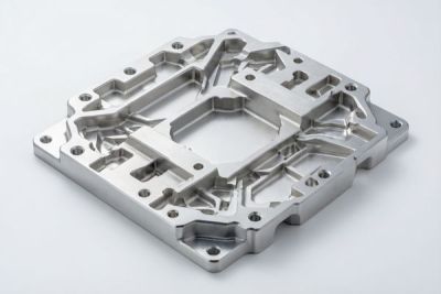
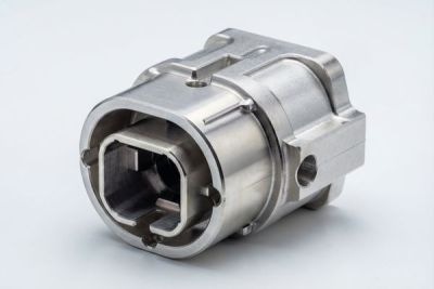
CNC Adapter Plates for Aerospace: Machining & Tolerances (2026 Guide)
An adapter plate looks simple on a drawing - a flat face, a few holes, maybe a counterbore. In an aerospace assembly it is anything but simple. It is the interface that decides whether a sensor sits exactly where the flight computer expects it, whether a mounting pattern lines up with a structure that was machined in a different country, and whether a joint stays sealed through years of thermal cycling and vibration. Get the plate wrong and you do not get a warning light; you get a misaligned payload, a leaking flange, or a rework loop that pushes your certification date back by months.
So the real question is not 'who can cut a flat plate cheapest?' It is 'who can hold the datums, the tolerances, and the finish batch after batch, and prove it with documents you can hand to your quality team?' This guide walks through how we, as a precision source factory, approach aerospace adapter plates - and how you should spec and qualify them. We keep it practical, the way one engineer explains a part to another.
We will cover what an adapter plate actually carries, how CNC precision machining holds the geometry that matters, how to pick between aluminum, titanium, and stainless for aerospace CNC parts, the tolerances that keep a plate seated, why stainless steel mirror finishing is a function and not a look, a design checklist so the part fits the first time, and the inspection and traceability questions that separate a real shop from a broker. For more on related component work, see our aerospace CNC machining guides.
Table of Contents
- 1. Why Adapter Plates Are the Quiet Heroes of Aerospace Assemblies
- 2. How CNC Precision Machining Shapes a Reliable Adapter Plate
- 3. Material Choices for Aerospace CNC Parts: Aluminum, Titanium, and Stainless
- 4. Tight Tolerance CNC: The Numbers That Keep an Adapter Plate Seated
- 5. Stainless Steel Mirror Finishing for Aerospace Adapter Plates
- 6. Custom CNC Parts: Designing an Adapter Plate That Fits the First Time
- 7. Aerospace CNC Parts Inspection and Traceability Checklist
- 8. Common Mistakes When Specifying Aerospace Adapter Plates
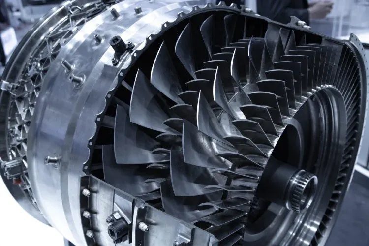
Aerospace CNC precision component
Why Adapter Plates Are the Quiet Heroes of Aerospace Assemblies
The part nobody photographs is often the part that decides whether the system works.
An adapter plate is the translation layer between two things that were never designed together: a sensor or subsystem built to its own envelope, and a structure built to a different one. It absorbs the mismatch. It carries loads, locates features, spreads clamp force, and seals interfaces - usually with no second chance, because once the structure is built there is nowhere else to put the correction.
What an adapter plate is actually doing
- Locating - it sets the position and orientation of the mounted unit to a known datum on the structure.
- Load transfer - it spreads bolt loads and reacts shear, moment, and vibration into the parent structure.
- Sealing - on fluid or pressurized interfaces it provides the flat-face seal that stops leaks at altitude.
- Thermal management - it can act as a heat path or a thermal break depending on the material you choose.
- Risk isolation - a cheap, re-machinable plate protects an expensive, hard-to-replace assembly.
The lesson for a buyer is that the plate is a system item, not a commodity. The value you are buying is repeatability: the tenth plate is identical to the first, and every one comes with a paper trail. That is what keeps your assembly line moving and your audit clean.
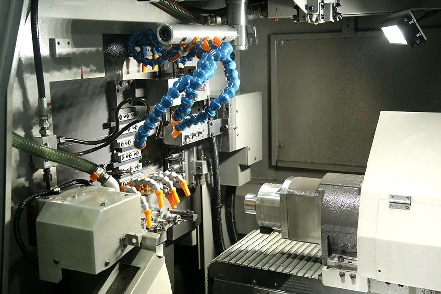
Aerospace CNC precision component
How CNC Precision Machining Shapes a Reliable Adapter Plate
A reliable plate is designed in the process, not chased after it with handwork.
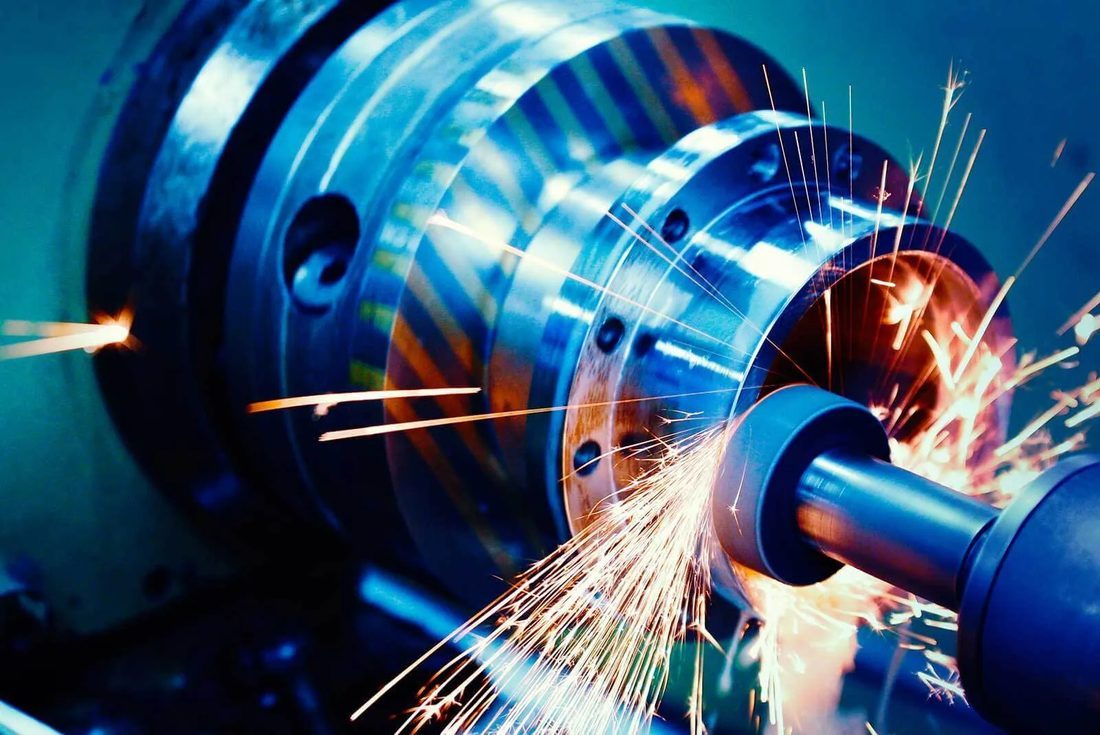
CNC precision machining earns its keep on adapter plates because the value is in relationships between features - hole pattern to face, bolt circle to counterbore, datum to datum - not in any single dimension. Those relationships are only as good as the setup that held the part. The moment you release and re-clamp, you introduce the chance of a datum shift.
The three-stage machining flow we use
- Rough and face in one clamp - establish the primary datum face and the outer profile before anything else, so every later feature references the same surface.
- Drill, bore, and counterbore the feature group - keep the bolt pattern and bores on the same setup so true position stays tied to the datum face.
- Finish and verify - take the final light cut on seats and faces, then inspect on a CMM against the full datum report rather than a single sample.
Why a single setup beats re-fixturing
Every re-clamp on a 3-axis machine can introduce 0.02 to 0.05 mm of shift between feature groups. On a plate whose whole job is holding features true to each other, that is the difference between a clean assembly and a hand-lapped one. Where a plate has angled bosses or features on both faces, we move to 5-axis so the part never leaves its first datum.
| Approach | 3-axis (multi-setup) | 5-axis (single setup) |
|---|---|---|
| Datum shift between groups | 0.02 to 0.05 mm per re-clamp | None after first clamp |
| Typical positional accuracy | ±0.01 mm | ±0.005 mm |
| Best for | Flat plates, simple brackets | Plates with features on two faces |
| Our cycle note | Cheaper per part, slower total | Faster to qualified, less rework |
Material Choices for Aerospace CNC Parts: Aluminum, Titanium, and Stainless
The material is a stiffness, weight, and corrosion decision long before it is a machining decision.
For aerospace CNC parts, the three materials we reach for most on adapter plates each solve a different problem. None is 'best' - the right call depends on what the plate is fighting: mass, stiffness, corrosion, or a combination.
Aluminum 7075-T6 and 6061-T6
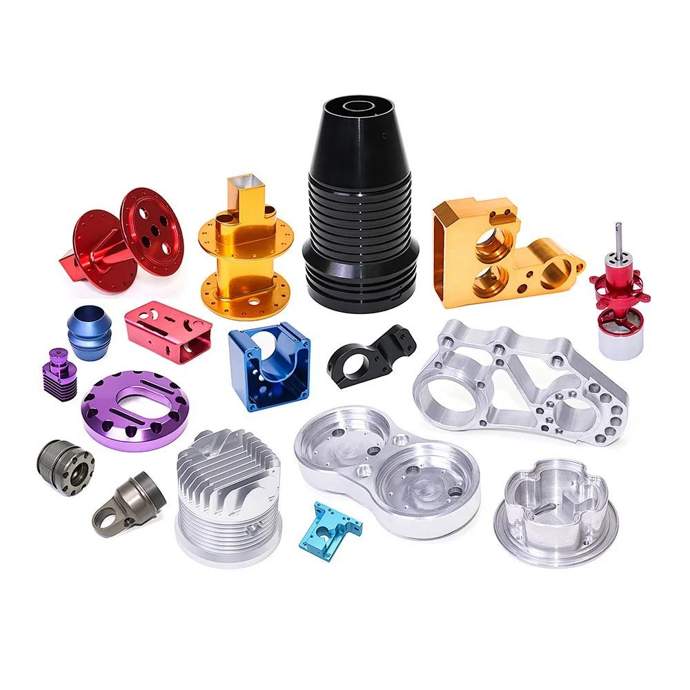
6061-T6 is the default for most plates: stable, easy to hold to tight tolerance, and kind to your budget. 7075-T6 steps in where yield strength matters and you can protect it with anodize, since its corrosion resistance is lower. We anodize most aluminum plates - Type II for a durable matte finish, Type III hard coat where the surface sees abrasion. Remember the coating adds a few microns, so we machine bores undersize and let the anodize bring them to nominal.
TC4 titanium
Titanium gives you roughly double the specific stiffness of aluminum for bending-limited plates, plus excellent corrosion resistance with no coating. The cost is machinability: it work-hardens, runs hot, and eats tool life, so cycle times run two to three times an equivalent aluminum part. We steer customers to titanium only when stiffness-to-weight or corrosion genuinely drives the design.
17-4PH and 316L stainless
When the plate must resist corrosion without a coating, or when you need the magnetic and surface properties stainless offers, we use 17-4PH (precipitation-hardened, strong) or 316L (austenitic, polish-friendly). Stainless is heavier, but for fluid-sealing faces and marine or de-iced environments it is often the only safe choice.
| Material | Density g/cc | Why use it | Watch out for |
|---|---|---|---|
| 6061-T6 aluminum | 2.70 | Most plates; cheap, stable, easy tolerance | Lower strength vs 7075 |
| 7075-T6 aluminum | 2.81 | High-stress plates, yokes | Corrosion; anodize required |
| TC4 titanium | 4.43 | Stiffness-to-weight, no coating | 2 to 3x cycle time, heat |
| 17-4PH stainless | 7.78 | Strong, corrosion-resistant, heat-treatable | Heavy, harder to polish |
| 316L stainless | 8.00 | Polish-friendly, biocompatible | Heaviest; slower to machine |
Pros
- Aluminum: fast, cheap, easy tolerance
- Titanium: stiff per gram, no coating needed
- Stainless: corrosion-proof without coating
- Each maps to a clear engineering need
Cons
- Aluminum: weak alone, needs anodize
- Titanium: slow and hot to machine
- Stainless: heavy, slower cycle
- Wrong choice quietly ruins the design
Aerospace CNC precision component
Tight Tolerance CNC: The Numbers That Keep an Adapter Plate Seated
Tolerance is a budget. Spend it where the assembly depends on it, and nowhere else.
Tight tolerance CNC is what lets an adapter plate do its job repeatably - but only if the tolerance is matched to the function. Tighter is not automatically better; it has to serve a purpose, or you are paying for scatter that nobody reads.
The features we actually hold tight
| Feature | Typical tolerance | Why it matters |
|---|---|---|
| Bolt-circle true position | ±0.03 mm | Pattern has to mate with the structure |
| Seat / pilot diameter | h7 / ±0.005 mm | Locates the mounted unit precisely |
| Seat flatness | 0.02 mm over face | Even clamp load, no rocking |
| Counterbore depth | ±0.05 mm | Bolt head sits flush, no tilt |
| Thread form | ISO 2 / 3A | Engagement and torque control |
We routinely hold ±0.005 mm on critical diameters and positions for these plates, verified by CMM and, where finish matters, by profilometry - not estimated. Batch parts get in-process gauging and lot-level CMM audits so a drift in the process shows up before a bad lot ships.
The cheapest adapter plate is the one that passes qualification the first time - because the second time costs you a certification date.
Stainless Steel Mirror Finishing for Aerospace Adapter Plates
On a sealing or fluid face, surface roughness is where leaks and corrosion start.
Stainless steel mirror finishing is often filed under 'looks nice.' On aerospace plates it is a function. A rougher face (higher Ra) gives a fluid somewhere to weep and gives corrosion a place to start; a mirror face down to Ra 0.2 micrometer (what we call 8K) seats a gasket better, cleans easier, and resists attack far longer.
How we reach a true mirror finish
- Start with the right grade - 316L or 17-4PH machined to a clean baseline so polishing has little to remove.
- Machine to a fine ground state (Ra around 0.4 micrometer) before any chemical step.
- Passivate per ASTM A967 to rebuild the chromium-oxide layer that makes stainless 'stainless'.
- Electropolish to level micro-peaks and drop Ra toward 0.2 micrometer.
- Verify with a profilometer - we do not guess the number, and we record it on the inspection report.
| Finish grade | Typical Ra | Where it is used |
|---|---|---|
| Standard machined | 0.8 micrometer | Non-critical structural faces |
| Fine ground | 0.4 micrometer | Handled, non-sealing faces |
| Mirror (8K) | 0.2 micrometer | Sealing faces, fluid paths, optics seats |
When you specify a sealing or fluid plate, write the Ra target on the drawing. 'Smooth' is not a tolerance; 'Ra 0.2 micrometer max' is. A serious shop will verify it and hand you the number.
Aerospace CNC precision component
Custom CNC Parts: Designing an Adapter Plate That Fits the First Time
Most adapter-plate delays are decided at the drawing stage, not on the shop floor.
As a custom CNC parts supplier we would rather spend an hour on your drawing than a week on your rework. Design for manufacture and the plate fits the first time; design against it and you discover the conflict at assembly. The good news is that most adapter-plate traps are easy to avoid if you know they exist.
Design rules we send back with every quote
- Call out datums explicitly - pick one primary face and chain everything to it.
- Tolerance the relationships, not the features - true position beats a stack of plus-minus callouts.
- Avoid sharp internal corners - end mills leave a radius; draw the radius you can accept.
- Decide coated vs bare condition before quoting - anodize grows the bore, hard coat grows it more.
- Specify the Ra on any sealing face in numbers, never as a word.
- Keep wall thickness sane for the material - 0.8 mm minimum in aluminum, 0.6 mm in titanium.
A shop that pushes back on your drawing with specifics is doing you a favor. One that says 'no problem, we can do anything' and asks no questions is the one that will surprise you at first article.
Aerospace CNC Parts Inspection and Traceability Checklist
Copy this and send it to every shop on your shortlist. The answers sort them fast.
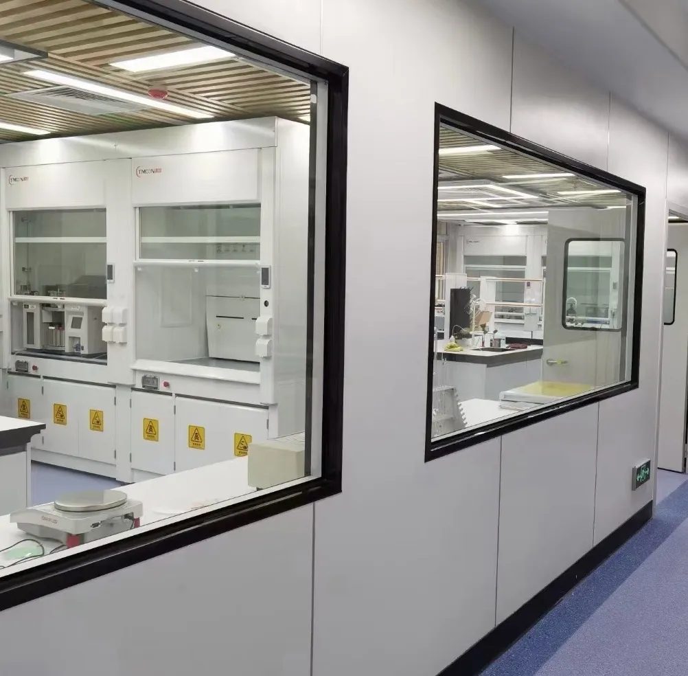
For aerospace CNC parts, documentation is part of the product. The part that arrives without a traceable history is not finished, no matter how good it looks. The checklist below is what we are happy to answer with redacted real records - and the fastest way to find out who is a real source factory and who is a broker with a logo.
- Can they show ISO 9001 (and ISO 13485 or AS9100 experience) with real QMS records?
- Do they machine your grade regularly, not as a one-off experiment?
- Will they provide a CMM first-article report with full datum references?
- Do they state and verify an Ra target with a profilometer when you ask?
- Will they supply FAI, in-process SPC, and batch traceability on every lot?
- Are tolerances quoted against your drawing, not a generic 'we are precise'?
- Can they support prototype to production without re-qualifying the process?
- Do they answer engineering questions directly, with numbers, not sales talk?
Documents a serious supplier should hand you
| Document | What it proves |
|---|---|
| Material mill certificate | The grade (e.g. 7075-T6, 316L) is genuine and from a known melt. |
| First-article inspection (FAI) | The first run matched your drawing before volume started. |
| In-process SPC | Tolerances stayed in control across the batch, not just on one part. |
| Passivation / finish report | Surface treatment was done to spec and verified (ASTM A967). |
| Certificate of Conformance (CoC) | The shipped lot meets every requirement on the PO. |
Aerospace CNC precision component
Common Mistakes When Specifying Aerospace Adapter Plates
Most failures we see were decided at the sourcing stage, not on the shop floor.
- Chasing the lowest bid - the saving evaporates in rework, delays, and re-certification.
- Treating ISO 9001 as a box to tick instead of a system to verify with documents.
- Skipping first-article inspection to 'save time' - it is the cheapest insurance you have.
- Leaving finish as 'smooth' on the drawing, then arguing about it after shipment.
- Forgetting coated vs bare tolerance on anodized aluminum bores.
- Drawing sharp internal corners that no end mill can produce as drawn.
- Ignoring communication - a shop that is vague before the PO stays vague after it.
None of these are technical mysteries. They are habits - and the disciplined shop you choose should make the right habit the easy default. The plate that fits the first time is the one whose spec was honest from the start.
Aerospace CNC precision component
Aerospace CNC precision component
Aerospace CNC precision component
Aerospace CNC precision component
FAQ: adapter plates & Aerospace Buyer Questions
A: We routinely hold ±0.005 mm on critical diameters and positions and ±0.03 mm on bolt-circle true position for adapter plates, verified by CMM and profilometry rather than estimated. Non-critical features are left at commercial tolerance to keep cost and cycle sane.
A: It depends on what the plate fights. 6061-T6 covers most plates cheaply and stably; 7075-T6 where yield strength matters (anodize required); TC4 titanium for stiffness-to-weight or corrosion without coating; 316L or 17-4PH stainless for sealing or corrosive environments. The right call is a system decision, not a default.
A: On a sealing or fluid face, a higher Ra gives leaks and corrosion a place to start. We take stainless sealing faces to a mirror (8K) Ra 0.2 micrometer via passivation per ASTM A967 plus electropolish, then verify with a profilometer and record it. Finish and chemistry are done together.
A: Yes. We supply material mill certificates, a CMM first-article report with full datum references, in-process SPC for batch parts, a passivation/finish report, and a Certificate of Conformance - so any shipped lot can be traced from raw bar to finished plate.
A: Where a plate has features on two faces or multiple feature groups that must stay mutually true, we use 5-axis machining so the part never leaves its first datum. That holds positional accuracy to ±0.005 mm across all faces and removes the 0.02 to 0.05 mm shift each re-clamp would introduce.
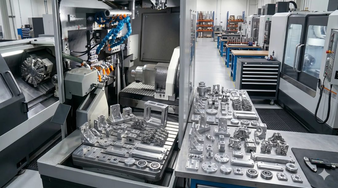
A: We run first-article inspection on new designs, support low-volume custom runs, and scale to monthly volume while keeping the same documented process and traceability. Our floor of 60+ CNC machines and 4,000 m2 plant lets a program grow without re-qualifying the source.
Ready to spec your aerospace adapter plate the right way? Send us your drawing and we will return a free DFM review with material, tolerance, and finish recommendations - no obligation, just a clear engineering answer from a 15-year precision shop.
Request a Free CNC Quote