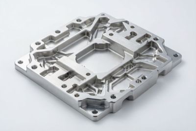
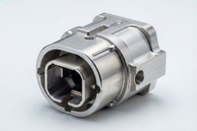
CNC Aluminum Heat Sinks and EMI Shielding Enclosures: A 2026 Technical Guide
If your board keeps throttling, or your RF module fails pre-compliance testing at 2.4 GHz, the problem is rarely the chip. Nine times out of ten it is the box around it. The electronic housings you specify decide how heat leaves the system and how much interference stays out — and those two jobs are in quiet conflict.
This 2026 guide walks you, the design engineer or procurement lead, through the machining decisions that actually move the needle: fin geometry and base flatness for CNC heat sinks, seam continuity and coating for EMI shielding, and the micron-level tolerances that keep connector machining signal-clean. We will use real numbers, not marketing claims.
By the end you should be able to read a supplier's quote and know exactly which line items protect your yield — and which are padding. Everything below is grounded in what a 60-machine CNC source factory in Dongguan actually holds to: Ra 0.2 µm mirror finishes, ±0.005 mm tolerances, and ISO 13485 / ISO 9001 discipline.
Table of Contents
- 1. Why Electronic Housings Decide Your Device's Thermal and Signal Integrity
- 2. CNC Heat Sinks: How Fin Geometry and Base Flatness Move Heat
- 3. EMI Shielding: How Machined Enclosures Block Interference
- 4. Aluminum CNC Machining for RF and Communication Enclosures
- 5. Connector Machining: Tolerances That Keep Signals Clean
- 6. Communication Enclosures: A Buyer's Sourcing Checklist
- 7. EMI Shielding vs CNC Heat Sinks: Which to Prioritize for Your Build
- 8. Choosing Between Electronic Housings and Communication Enclosures
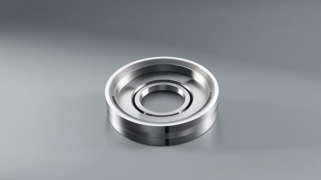
Electronics&Communication AI part image
Why Electronic Housings Decide Your Device's Thermal and Signal Integrity
The enclosure is not packaging — it is part of the circuit.
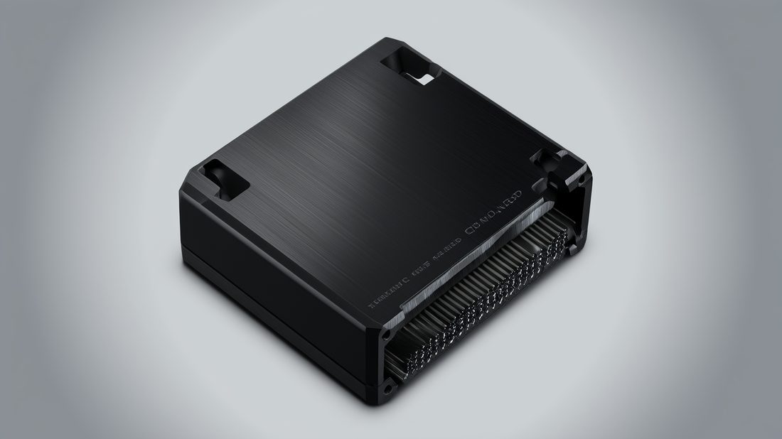
When you source electronic housings, you are really buying three overlapping functions in one block of metal: a thermal path, a Faraday cage, and a mechanical datum. A wall that is too thick adds mass and cost but helps shielding; a wall that is too thin radiates and flexes. The trick is to let machining — not post-assembly guessing — set those trade-offs on purpose.
- Electronic housing
- The machined metal shell that mechanically supports a PCB or module while managing heat flow and electromagnetic containment.
- Thermal resistance (°C/W)
- How much temperature rise you pay for each watt dissipated; lower is better and is driven mostly by fin area and base flatness.
Three failure modes buyers actually meet
- Hot-spot throttling: the IC touches its limit because the heat-sink base was not flattened to spec, so the thermal interface material bridges a gap it was never meant to fill.
- Radiated emissions: seams and lids are bolted on with gaps wider than a wavelength fraction, so the 'shield' leaks like a sieve at GHz frequencies.
- Fit failures: panel-mount connectors sit proud or recessed because the machined pocket tolerance was looser than the gasket could absorb.
All three trace back to one root cause: the housing was treated as a commodity. When you brief a CNC shop on a housing, you are briefing them on thermal, RF, and mechanical performance at once. The sections below show how each is machined and verified.
| Material | Thermal conductivity (W/m·K) | Shielding mass benefit | Typical use in housings |
|---|---|---|---|
| Aluminum 6061-T6 | 167 | Light, good | General electronic housings, lids |
| Aluminum 7075-T6 | 130 | Light, stiff | Structural RF enclosures |
| Stainless 304 (mirror Ra 0.2 µm) | 16 | Heavy, corrosion-proof | Medical / wet-environment housings |
| Copper C110 | 390 | Heavy, best conduction | High-power base plates |
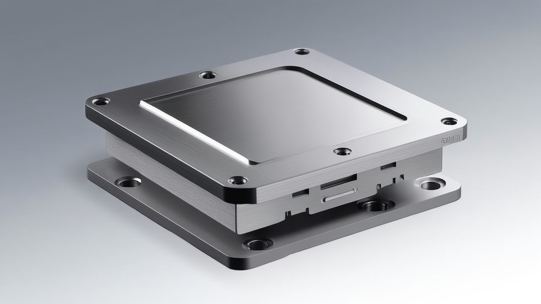
Electronics&Communication AI part image
CNC Heat Sinks: How Fin Geometry and Base Flatness Move Heat
A heat sink is 90% geometry and 10% material.
Step 1 — Choose the alloy and the thermal budget
Start from your worst-case wattage, not your average. A sink sized for 8 W that sees 12 W in a sealed enclosure will quietly cook the part. Aluminum CNC machining gives you 167 W/m·K in 6061 — enough for most power bricks, LED drivers, and comms modules — and lets you taper the fin count to the space you actually have.
Step 2 — Mill the fins without starving the base
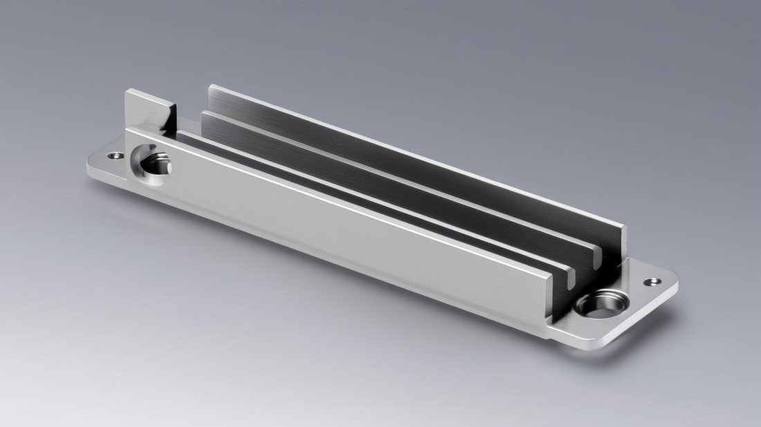
Fin spacing is a machining trade, not just a thermal one. Tight fins (1.5–2.0 mm pitch) raise surface area but raise tooling time and trap dust; wide fins are cheap but waste volume. On a 5-axis or turn-mill cell we typically land at 2.0–3.0 mm pitch for sinks under 40 mm tall, which balances airflow and cycle cost. Remember: fins only work if the base under them is solid and flat.
Step 3 — Flatten the base to ±0.005 mm
This is the step lazy quotes skip. A base flatness of ±0.005 mm (5 microns) lets the thermal interface material do its job instead of bridging an air gap. At Dongguan Licun Technology we hold that flatness on 60+ CNC machines and verify it per batch, because a 0.02 mm bow can add 0.5 °C/W of resistance you never see on the datasheet.
| Fin pitch (mm) | Relative surface area | Thermal resistance (°C/W, est.) | Machining cost index |
|---|---|---|---|
| 4.0 (wide) | 1.0× | 1.8 | 1.0× |
| 3.0 (medium) | 1.4× | 1.3 | 1.3× |
| 2.0 (tight) | 1.9× | 0.9 | 1.8× |
| 1.5 (very tight) | 2.3× | 0.7 | 2.6× |
EMI Shielding: How Machined Enclosures Block Interference
Shielding is continuity, not just conductivity.
EMI shielding works by giving interference a low-impedance path around your circuit. A milled aluminum box is already conductive, but the seams, lids, and connector cut-outs are where signals leak. The job of communication enclosures design is to keep that path unbroken across every joint.
- Shielding effectiveness (dB)
- How many decibels of field strength a barrier removes; 40 dB ≈ 99% attenuation, 60 dB ≈ 99.9%.
- Seam continuity
- Electrical contact maintained across a joint, usually by controlled surface flatness and conductive gaskets.
Where the leaks actually are
- Lid seams with gap > 0.1 mm at GHz frequencies act as slot antennas.
- Unplated screw bosses interrupt current flow around corners.
- Connector cut-outs without a grounded bezel let common-mode noise ride the cable.
| Shielding method | Typical effectiveness | Cost | Best for |
|---|---|---|---|
| Machined conductive seams + gasket | 60–80 dB | Medium | Repeatedly opened enclosures |
| Electroless nickel / ASTM A967 passivation | 40–60 dB | Low–Medium | Sealed comms housings |
| Conductive spray coating | 30–50 dB | Low | Plastic-backed parts |
| Die-cast + gasket | 50–70 dB | High tooling | High-volume consumer |
Electronics&Communication AI part image
Aluminum CNC Machining for RF and Communication Enclosures
For RF, the wall itself is part of the antenna system.
When you brief a shop on aluminum CNC machining for RF work, you are asking them to hold dimensional and surface specs that directly affect return loss. A waveguide wall that is 20 microns out of flat at a seam can detune a 5 GHz cavity. That is why RF communication enclosures are held to the same ±0.005 mm discipline we apply to medical and aerospace parts.
Why aluminum wins for RF enclosures
Aluminum is light, machines cleanly to fine finishes, and its native oxide is stable — ideal for sealed comms gear mounted on towers or inside vehicles. For higher shielding you can step up to 7075-T6, which keeps stiffness when you thin the walls to save weight.
Surface finish: from Ra 0.6 µm to 8K mirror Ra 0.2 µm
Our standard mirror is Ra ≤ 0.6 µm; the top tier is an 8K mirror at Ra 0.2 µm. For most enclosures Ra 0.6 µm is plenty, but for sliding lids, contact seams, and optical-adjacent parts the 0.2 µm face improves both gasket seating and corrosion behavior. After machining we apply ASTM A967 passivation where the spec calls for it, which also stabilizes the surface for shielding coatings.
| Aluminum grade | Strength (MPa) | Machinability | RF enclosure fit |
|---|---|---|---|
| 6061-T6 | 276 | Excellent | General comms, lids |
| 7075-T6 | 503 | Good | Stiff thin-wall RF cans |
| 5052-H32 | 228 | Very good | EMI gasket frames |
Connector Machining: Tolerances That Keep Signals Clean
A connector pocket cut 30 microns off is a signal you will never get back.
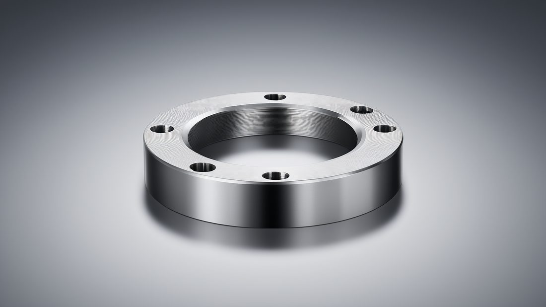
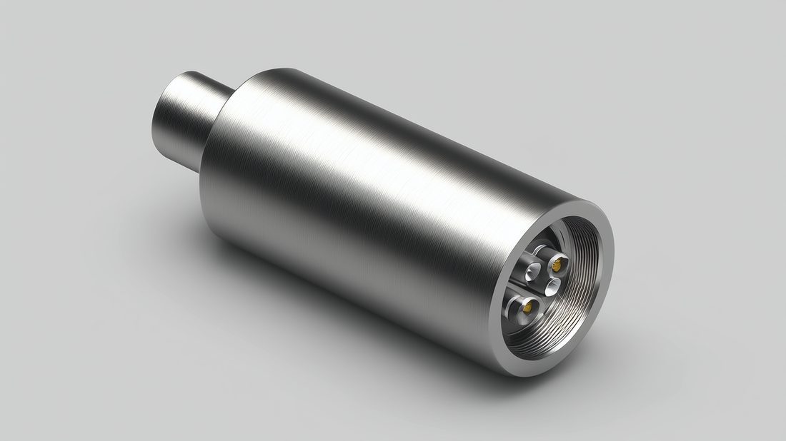
Connector machining is where tolerance discipline meets RF reality. The pocket that seats a panel-mount SMA or a board-to-board header must hold position and depth tightly, or you introduce reflections and mechanical strain. We hold these pockets to ±0.005 mm and verify the first article before any production run.
Pin-hole position tolerance vs frequency
As frequency climbs, the allowable position error shrinks. A hole that is fine at 100 MHz can wreck a 6 GHz link. This is why connector machining for communication enclosures is planned on the same tolerances as the RF cavity — they are the same signal path.
| Frequency band | Max pin-position error | Machining approach |
|---|---|---|
| ≤ 100 MHz | ±0.05 mm | Standard 3-axis mill |
| 100 MHz – 2 GHz | ±0.02 mm | 3-axis + reamed holes |
| 2 – 6 GHz | ±0.01 mm | 5-axis / turn-mill, probed |
| ≥ 6 GHz | ±0.005 mm | Swiss-type + CMM verify |
Electronics&Communication AI part image
Communication Enclosures: A Buyer's Sourcing Checklist
Before you release a PO, ask for these five things.
The fastest way to protect your build is to make the supplier prove the hard numbers up front. Use this checklist when you request a quote for communication enclosures or electronic housings — if a vendor cannot answer, that is your red flag.
- Material cert (mill test report) for the exact aluminum grade — not 'aluminum' generically.
- Flatness and position tolerance data, with the inspection method (CMM / gauge) named.
- Surface finish spec in Ra, not just 'polished' or 'smooth'.
- Passivation / coating standard cited (e.g., ASTM A967) where shielding depends on it.
- Batch-level material traceability and a first-article report before volume runs.
Common mistakes buyers make
- Specifying a cosmetic finish (Ra 0.8 µm) where a functional seam (Ra 0.2 µm) was needed — and paying for the wrong thing.
- Treating the heat sink and the shield as two separate POs from two shops, so the base never matches the lid.
- Asking for 'EMI shielding' without naming the frequency and dB target, which gets you a box that passes nothing.
- Skipping first-article inspection to save a week, then eating a 5,000-piece scrap run.
EMI Shielding vs CNC Heat Sinks: Which to Prioritize for Your Build
They fight each other — so decide the winner on purpose.
Here is the quiet conflict: maximizing EMI shielding wants thick, continuous, gasketed metal; maximizing CNC heat sinks wants thin walls and open fin stacks. You cannot max both. The table below helps you decide which one your application must win.
| Project requirement | Recommended priority | Why it wins |
|---|---|---|
| Battery-powered IoT sensor | Heat sink first | Thermal margin beats rare interference in the field |
| Vehicle comms module | EMI shielding first | Regulatory emissions are pass/fail and costly to fix late |
| Sealed indoor gateway | Balanced | Both matter; thin-wall RF can + internal sink |
| Medical near-patient device | Shielding + clean finish | EMC + biocompatible surface take priority |
Choose heat-sink-first if…
- Your device sits in a thermally bounded enclosure with no forced airflow.
- The chip's junction temperature is already within 10 °C of its limit at nominal load.
- Your RF environment is quiet (rural, shielded lab, single-device).
Choose EMI-shielding-first if…
- You must pass FCC / CE / CISPR pre-compliance at 1 GHz or above.
- The product shares a chassis with motors, inverters, or radios.
- Field returns from interference would cost more than the gasket and plating.
Electronics&Communication AI part image
Choosing Between Electronic Housings and Communication Enclosures
Same factory, two briefs — know which you are writing.
Buyers often use the two terms interchangeably, but the brief differs. A general electronic housing optimizes for mounting, cooling, and looks; a communication enclosure optimizes for RF integrity and shielding continuity. Knowing which you need changes the machining plan from line one.
| Dimension | Electronic housings | Communication enclosures |
|---|---|---|
| Primary goal | Protect + cool + mount | Contain RF + block EMI |
| Tolerance focus | Fit and flatness | Seam continuity + position |
| Finish driver | Aesthetics + corrosion | Shielding + gasket seat |
| Typical spec call-out | Ra 0.6 µm, ±0.01 mm | Ra 0.2 µm seam, ±0.005 mm |
Pros
- A single CNC source can deliver both under one quality system (ISO 9001 / 13485).
- Combining the PO reduces interface risk between sink and lid.
Cons
- Over-specifying shielding on a quiet product wastes plating cost.
- Under-specifying finish on a comms part fails compliance late.
Electronics&Communication AI part image
Electronics&Communication AI part image
Electronics&Communication AI part image
Electronics&Communication AI part image
FAQ: electronic housings & Electronics&Communication Buyer Questions
A: Hold the base flatness to ±0.005 mm (5 microns). That lets the thermal interface material bridge properly; a looser ±0.02 mm base can add roughly 0.5 °C/W of resistance and cause throttling you will not see on paper.
A: No. Aluminum is conductive, but a milled box only shields if its seams, lids, and connector cut-outs maintain electrical continuity — usually via controlled flatness and a conductive gasket. A loose lid can test 10 dB worse than a gasketed one.
A: 6061-T6 is the default: good conduction (167 W/m·K), excellent machinability, and light weight. Step up to 7075-T6 when you need stiffness in thin RF walls, or 5052-H32 for EMI gasket frames.
A: For 2–6 GHz use ±0.01 mm pocket position verified on a 5-axis or turn-mill cell; at 6 GHz and above, hold ±0.005 mm and confirm with CMM first-article inspection.
A: Request the material mill cert, named flatness/position tolerances with inspection method, Ra surface finish (not 'polished'), any passivation standard such as ASTM A967, and batch traceability with a first-article report.
A: Yes. A source factory running 60+ CNC machines under ISO 9001 / ISO 13485 can deliver both under one quality system, which reduces the interface risk between the sink base and the lid — often at lower total cost than two suppliers.
Send us your drawing for a free DFM review — we will flag thermal, shielding, and tolerance risks before you release the PO.
Request a Free CNC Quote