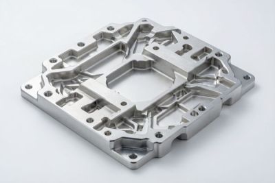
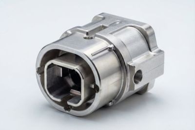
CNC Timing Pulleys: Machining & Tolerances for Fluid Control Valves (2026 Guide)
In a fluid control system, a valve that drifts out of position by a fraction of a degree can mean a metering pump that over-doses, a position indicator that lies, or a process line that quietly loses its setpoint. At the heart of many of these mechanisms sits a small, often overlooked timing pulley. It is the part that translates motor rotation into exact, repeatable valve motion. If you are specifying parts for actuators, metering pumps, or automated valve trains, the pulley is not a commodity. It is the link that decides whether your motion stays synchronized.
This guide is written the way an engineer would explain it to a colleague. We cover how CNC precision machining turns a bar of stainless steel into a timing pulley you can trust at plus or minus 0.005 mm, why surface finish down to Ra 0.2 micrometre mirror matters in a wetted or washdown environment, how to choose between a machined pulley and other drive options, and the checklist we use to qualify a supplier of fluid control and valve CNC parts. We keep it practical and honest, with real numbers rather than adjectives.
We are Dongguan Licun Technology Co., Ltd. (brand LusterControl), a Dongguan source factory that has machined stainless steel since 2015. So we speak from the shop floor, not a catalog. By the end you should be able to write a pulley specification that a good shop can actually hold, and to spot the red flags before you ever place an order.
Table of Contents
- 1. Why Timing Pulleys Are Critical to Fluid Control and Valve CNC Parts
- 2. How CNC Precision Machining Shapes a Reliable Timing Pulley
- 3. Tight Tolerance CNC: What Accuracy Your Valve Timing Pulley Actually Needs
- 4. Stainless Steel Mirror Finishing for Fluid Control and Valve Pulleys
- 5. Custom CNC Parts: Designing Timing Pulleys for Metering Pumps and Actuators
- 6. Timing Pulleys vs Other Drive Options for Valve Actuation: A Comparison
- 7. A Buyer's Checklist for Sourcing Fluid Control and Valve CNC Parts
- 8. Common Mistakes Engineers Make When Specifying Timing Pulleys
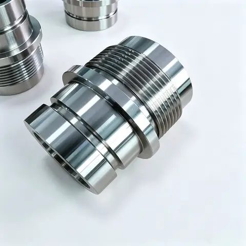
Fluid Control&Valve CNC precision component
Why Timing Pulleys Are Critical to Fluid Control and Valve CNC Parts
A pulley that slips or wobbles turns a precise actuator into a guessing game.
A timing pulley does one job that sounds simple and is anything but: it moves rotation from a motor to a shaft while preserving the exact phase relationship between them. In valve actuation that phase is the valve position. In a metering pump it is the dose. In a flow meter it is the pulse count that becomes your billing or your batch record. When the tooth profile is accurate and the bore runs true, the system stays in sync for millions of cycles. When it is not, you get backlash, drift, and noise that shows up first as scrap and later as a field failure.
Where you actually find them
- Valve actuator drives, where a stepper or servo has to park a ball or butterfly valve at a precise angle.
- Metering and diaphragm pumps, where pump stroke must stay locked to motor rotation for accurate dosing.
- Flow-meter pulse wheels, where each tooth passing a sensor is a counted volume increment.
- Position-indicator gears on manual or automated valve trains that report open, closed, or in-between.
- Lab and analytical instrument feed systems where repeatability beats raw speed.
The takeaway is simple. The pulley looks cheap and it is small, but it is a precision component. Treat it like one and your whole valve assembly behaves. Treat it like a bolt-on and you will spend the savings on troubleshooting.
Fluid Control&Valve CNC precision component
How CNC Precision Machining Shapes a Reliable Timing Pulley
The process you choose decides whether the tolerance survives contact with the real world.
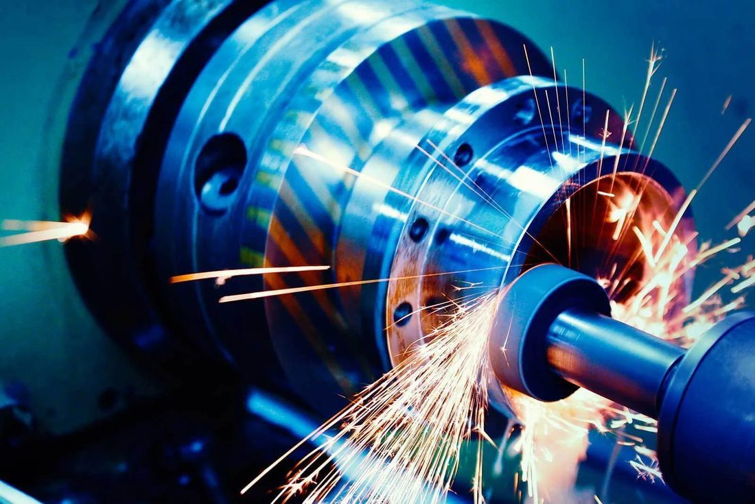
A reliable timing pulley is not the product of one magic machine. It is the product of choosing the right sequence so that every critical feature is referenced to the same datum. For a pulley, the bore, the tooth pitch circle, and the running faces all have to agree with each other, and the only way to guarantee that is to keep the part clamped to one datum through as many operations as possible.
From bar stock to finished pulley
- Select the grade. For dry actuator drives we often use free-machining 303; for wetted or corrosive service we move to 304 or 316L.
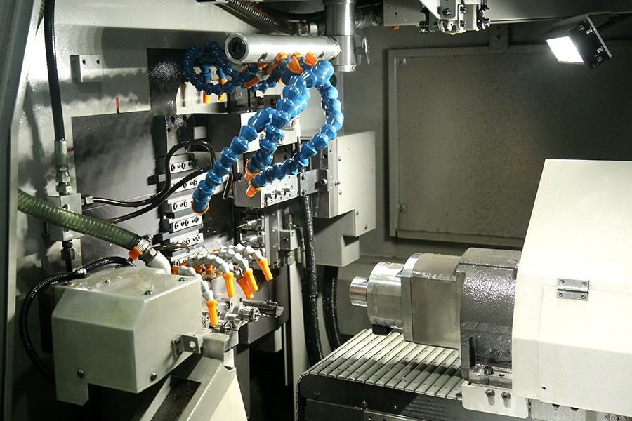
- Turn the bore and outer diameter on a Swiss-type or CNC lathe so the bore is true to the OD before any teeth exist.
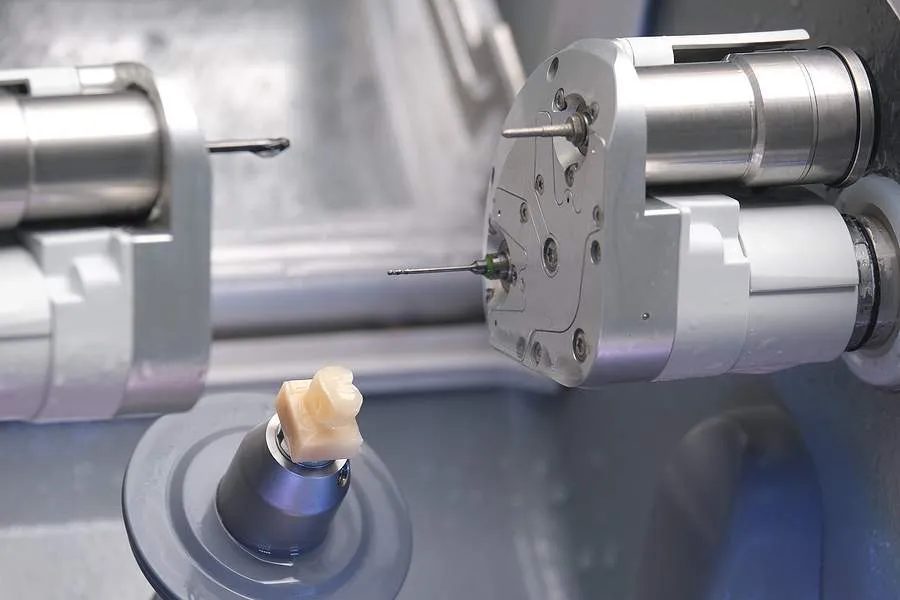
- Mill or hob the tooth profile on a 4 or 5 axis center, referencing the already-turned bore as the datum.
- Use turn-mill compound machining to add flanges, keyways, or hubs in the same clamp, protecting the stack-up of tolerances.
- Deburr and passivate to ASTM A967 so the part is clean and corrosion-resistant, not just shiny.
- Inspect with CMM for geometry and a profilometer for finish, because we do not guess the numbers that matter.
Why we combine operations
- Turn-mill compound
- A machine that turns and mills in one setup, so a part keeps one datum and tolerances do not accumulate from moving between machines.
- Swiss-type turning
- A sliding-headstock lathe ideal for long, slender, tightly toleranced shafts and small pulleys.
- Datum
- The reference surface or axis from which every other dimension is measured; protecting it protects your tolerance.
- ASTM A967
- The standard that defines how stainless steel is passivated to maximize corrosion resistance.
| Process | Best for | Typical tolerance | Volume |
|---|---|---|---|
| Swiss-type turning | Slender shafts, small pulleys | ±0.005 mm | Low to high |
| 5-axis milling | Complex hub and tooth forms | ±0.01 mm | Prototype to mid |
| Turn-mill compound | Pulley with milled hub or flange | ±0.008 mm | Mid to high |
| Passivate + electropolish | Final finish on 304 or 316L | Ra 0.2 µm | All |
For fluid control and valve CNC parts especially, combining operations in a single clamp reduces the error stack-up that comes from moving a part between machines. Process choice here is a quality decision, not just a cost one.
Tight Tolerance CNC: What Accuracy Your Valve Timing Pulley Actually Needs
Tighter is not automatically better. Tolerance has to serve a function.
Every tighter tolerance you put on a drawing costs money in cycle time, tooling wear, inspection, and scrap. The disciplined approach is to tighten only the features that actually control synchronization and fit, and to leave the rest at a sane commercial tolerance. A good supplier will tell you which features matter for your pulley and which are quietly wasting your budget.
Tolerances that matter by feature
| Feature | Typical tolerance | Why it matters |
|---|---|---|
| Bore diameter | ±0.005 mm | Runs true on the shaft, no wobble at speed |
| Tooth pitch circle | ±0.01 mm | Phase stays locked between motor and valve |
| Flatness of faces | ±0.01 mm | Belt tracks straight, no edge wear |
| Runout (TIR) | ±0.02 mm | Smooth running, low noise, long belt life |
| Keyway or slot | ±0.02 mm | Torque transfer without play |
- Backlash
- The lost motion between mating teeth before they engage; low backlash keeps valve position repeatable.
- Pitch
- The centre-to-centre distance between adjacent teeth; it must match your belt exactly.
- Runout (TIR)
- Total indicator reading; how far a feature wobbles as the part rotates.
Pros
- Predictable fit and phase
- Lower assembly scrap
- Easier validation and repeat orders
Cons
- Tighter features cost more to hold
- Not every feature needs them
- Inspection time grows with each tight callout
When you talk to a supplier about fluid control and valve CNC parts, ask them to mark up your drawing with the features they would hold tight and the ones they would relax. The answer tells you whether they understand your application.
Fluid Control&Valve CNC precision component
Stainless Steel Mirror Finishing for Fluid Control and Valve Pulleys
In a wetted or washdown valve environment, finish is a hygiene and corrosion issue, not a cosmetic one.
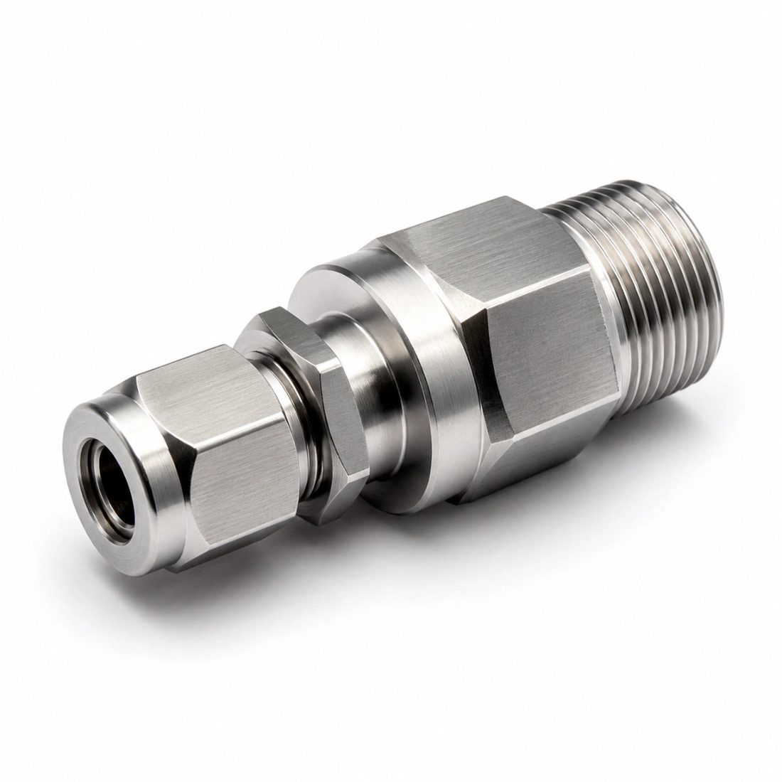
A timing pulley in a fluid path or a washdown area lives in contact with chemicals, moisture, and sometimes food or pharma-grade media. A rougher surface gives bacteria and corrosion a place to start, and it wears the belt faster. A mirror finish down to Ra 0.2 micrometre, what we call 8K, is smoother, easier to clean, and far more durable. That is why stainless steel mirror finishing belongs in the specification, not the sales brochure.
How we reach a true mirror finish
- Start with the correct grade, typically 304 or 316L for wetted service.
- Machine to a clean baseline so polishing has little material to remove.
- Passivate to ASTM A967 to rebuild the chromium-oxide layer that makes stainless resist corrosion.
- Electropolish to level micro-peaks and drop Ra toward 0.2 micrometre.
- Verify with a profilometer, because a guess is not a measurement.
| Finish grade | Typical Ra | Where it is used |
|---|---|---|
| Standard machined | 0.8 µm | Non-critical drive covers |
| Fine turned | 0.4 µm | Dry actuator housings |
| Mirror (8K) | 0.2 µm | Wetted, washdown, pharma, food valves |
For more on how a Dongguan source factory runs this discipline at scale, our Dongguan Licun Technology page lays out the plant, the certifications, and the process controls behind every part.
Custom CNC Parts: Designing Timing Pulleys for Metering Pumps and Actuators
Most pulley problems are decided at the drawing stage, not on the shop floor.
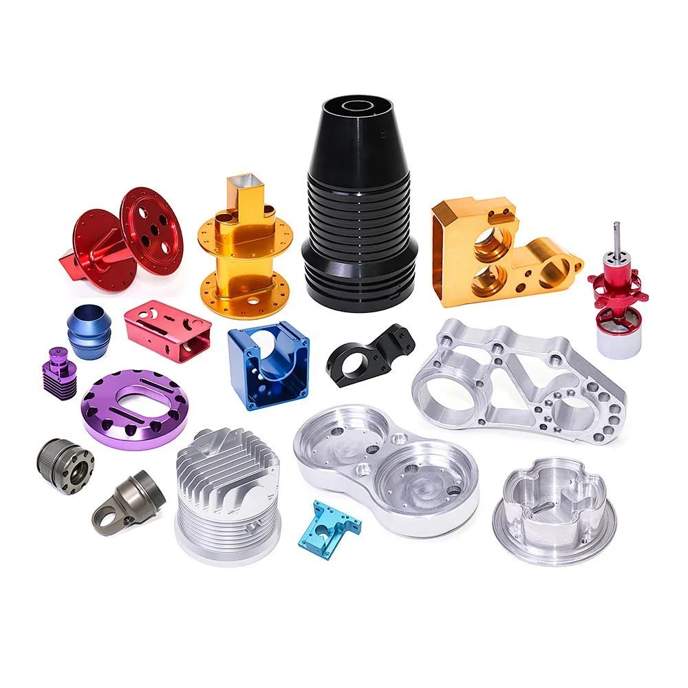
Off-the-shelf pulleys rarely fit a compact valve actuator or a tight metering-pump layout. Custom CNC parts let you integrate the hub, flange, bore, and tooth profile into one machined body, which removes joints that could loosen and datums that could shift. The design choices you make in CAD are what keep the part honest in the field.
Design choices that protect your tolerance
- Integrate the hub instead of pressing a separate one, so the bore and pitch never decouple.
- Use a press-fit or keyed bore sized to your shaft rather than a loose slip fit.
- Add a flange or web to retain the belt and shield the teeth from debris in the fluid path.
- Match the tooth profile (MXL, XL, HTD, or GT) exactly to your belt, not approximately.
- Call out finish only where the part is wetted or cleaned, to control cost.
Custom does not mean expensive when the volume is there. Because we run both small custom batches and half a million parts a month, a pulley design can grow from first prototype to full production without re-qualifying the source.
Fluid Control&Valve CNC precision component
Timing Pulleys vs Other Drive Options for Valve Actuation: A Comparison
The right drive is the one matched to your load, space, and accuracy need.
A timing pulley is not the only way to move rotation inside a valve assembly. Spur gears, direct-drive motors, and friction belts all exist, and each wins in a different scenario. The mistake is picking by habit instead of by requirement. Below is the honest trade for a fluid control context.
| Factor | Timing pulley | Spur gear | Direct drive |
|---|---|---|---|
| Synchronization | Excellent, low backlash | Good, needs precise mesh | Best, zero linkage |
| Space | Compact, centre distance flexible | Bulkier, fixed centres | Most compact at motor |
| Noise | Low | Higher whine | Silent |
| Maintenance | Belt wear over time | Lubrication needed | Near zero |
| Cost at volume | Low | Medium | High |
| Best use | Metering, positioning | High torque transfer | Ultra-precise servo valves |
Choose a timing pulley if
- You need synchronized motion between a motor and a valve without a rigid coupling.
- Space is tight and you want flexible centre distances.
- You want low noise and low cost at production volume.
- Your load is moderate and your priority is repeatable phase, not maximum torque.
Choose another option if
- You are transferring very high torque, where a gear or coupling is stronger.
- You need zero maintenance for the life of the unit, where direct drive wins.
- Tolerance to belt stretch over years would break your accuracy budget.
Pros
- Low cost, low noise, easy synchronization
- Flexible layout, simple assembly
Cons
- Belt wear needs a service interval
- Not for the highest torque loads
For a deeper look at related drive and transmission components, browse our technical guides on fluid control and valve CNC parts and precision transmission machining.
A Buyer's Checklist for Sourcing Fluid Control and Valve CNC Parts
Copy this and send it to every shop on your shortlist. The answers will sort them fast.
- Can they show ISO 9001 with real QMS records, and ISO 13485 where medical or pharma fluid service is involved?
- Do they machine 303, 304, and 316L stainless regularly, not as a one-off?
- Can they state a finish target such as Ra 0.2 to 0.4 micrometre and verify it with a profilometer?
- Will they passivate to ASTM A967 and document it, not just claim a bright look?
- Do they provide first-article inspection, SPC, and batch traceability on every lot?
- Are tolerances quoted against your drawing, with tight callouts only where motion depends on them?
- Can they support prototype to production without re-qualifying the process?
- Do they answer engineering questions with specifics, not sales talk?
A supplier that clears all eight is rare and worth keeping. One that stumbles on traceability, passivation, or finish verification should not be on a fluid control or valve program where a single bad lot becomes a recall.
Fluid Control&Valve CNC precision component
Common Mistakes Engineers Make When Specifying Timing Pulleys
Most failures we see were locked in at the sourcing stage, not on the shop floor.
- Chasing the lowest bid, when the saving evaporates in rework, delays, and validation restarts.
- Leaving finish as 'smooth' on the drawing, then arguing about it after shipment.
- Over-tolerancing every feature, which forces scrap and slows delivery for no functional gain.
- Ignoring backlash and pitch match, so the valve drifts even though each part 'measures fine'.
- Skipping first-article inspection to save time, which is the cheapest insurance you have.
- Forgetting traceability, so a single complaint becomes a full stop-ship instead of a targeted fix.
None of these mistakes are technical. They are habits, and the disciplined supplier you choose should make the right habit the easy default. That is the difference between a valve that works for years and one that becomes a service call.
Fluid Control&Valve CNC precision component
Fluid Control&Valve CNC precision component
Fluid Control&Valve CNC precision component
Fluid Control&Valve CNC precision component
FAQ: timing pulleys & Fluid Control&Valve Buyer Questions
A: We routinely hold plus or minus 0.005 mm on the bore and plus or minus 0.01 mm on tooth pitch circle and face flatness for valve pulleys, with runout controlled to plus or minus 0.02 mm. Every number is verified by CMM and profilometer rather than estimated.
A: For dry actuator drives, free-machining 303 is common. For wetted or corrosive service, 304 or 316L is the right choice, with 316L preferred for marine, pharma, or chemical lines because of its higher pitting resistance. The grade should match the media, not the price list.
A: In a wetted or washdown environment a rougher surface gives bacteria and corrosion a place to start and wears the belt faster. A mirror finish down to Ra 0.2 micrometre, our 8K, is smoother, easier to clean, and more durable. Always specify the Ra target and verify it.
A: Yes. We run first-article inspection on new designs, support low-volume custom runs, and scale to monthly volume while keeping the same documented process and batch traceability, so your program grows without re-qualifying the source.
A: Every lot is tied to its material mill certificate, the machine and operator that ran it, in-process inspection records, and a Certificate of Conformance. Any shipped part can be traced back to its full history, which is what a recall-ready program requires.
A: State the material grade, the exact tooth profile and pitch matched to your belt, the bore and keyway, the finish target such as Ra 0.2 micrometre where wetted, the tight tolerances only on features that control motion, and your volume. Send the drawing and a good shop will return a free DFM review before you cut metal.
Ready to turn your pulley drawing into a part you can trust at plus or minus 0.005 mm? Send us your drawing for a free DFM review with tolerance and finish recommendations. No obligation, just a clear engineering answer from LusterControl.
Request a Free CNC Quote