CNC Waveguide Components: Machining & Tolerances for Optical (2026 Guide)
If you build a laser module, a beam-delivery head, or a photonic instrument, the part you are most likely to under-specify - and later fight on the bench - is the waveguide body or its housing. It looks like a block with a couple of bores and a flange. But that component is the mechanical spine of your optical path: it carries the lens, sets the mirror angle, holds the fiber port, and decides whether your beam lands on the detector or a millimeter off in the dark.
This guide is written for the engineers and procurement leads who specify and buy these components, not for a catalog. We walk through what a CNC waveguide component actually does in an optical system, how precision machining holds its bores, flange, and alignment features within +/- 0.005 mm, why surface finish decides both scattered light and corrosion life, and the mistakes we see buyers make most often. The numbers are the ones we argue about with customers before the first blank is cut.
By the end you will have a checklist you can send to any machine shop - including our own - and a clear sense of what a good answer sounds like, whether you are sourcing a handful of housings for a prototype instrument or qualifying a high-volume run for a medical, semiconductor, or industrial optical product. A waveguide body only earns its place if its geometry is honest; the rest is detail.
Table of Contents
- 1. What Are CNC Waveguide Components and Why They Matter for Optical Systems
- 2. How CNC Precision Machining Builds Optical Waveguide Housings
- 3. Tight Tolerance CNC: Dimensional Control on Waveguide Bodies
- 4. Optical CNC Parts: Lens Barrels and Mirror Bases That Hold Alignment
- 5. Waveguide Components vs Cast Housings: A Buyer's Comparison
- 6. Custom CNC Parts: Designing Waveguide Flanges and Alignment Features
- 7. Stainless Steel Mirror Finishing for Optical Waveguide Surfaces
- 8. A Buyer's Checklist for Sourcing Tight Tolerance CNC Waveguide Components
- 9. Common Mistakes Buyers Make When Specifying Waveguide Components
Optical CNC precision component
What Are CNC Waveguide Components and Why They Matter for Optical Systems
The waveguide body is the mechanical spine of your optical path.
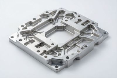
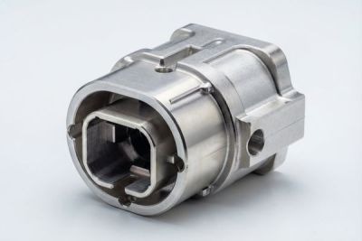
A CNC waveguide component is a precision-machined housing, bench, or manifold that locates and protects the parts of an optical path - lenses, mirrors, beamsplitters, fiber ports, and detectors - so the beam goes where you designed it. In a laser cavity it is the block that seats the mirror and holds the bore the beam passes through. In a fiber transceiver it is the flange that aligns the ferrule to within microns. In a LiDAR scanner it is the base that keeps the rotating mirror true at speed. In every case it does two jobs at once: it is a load path that resists shock and thermal drift, and it is a locating fixture that sets where each optical element sits relative to the rest of the system.
Where you actually find them in an optical system
- Laser cavities and beam-delivery heads where the mirror seats and bore must stay coaxial.
- Fiber-optic transceiver flanges that align the ferrule against the detector window.
- Lens barrels and cell rings that hold a singlet or doublet at its design focus.
- Mirror bases and kinematic mounts that set a reflector's angle to arc-seconds.
- Spectrometer and interferometer benches where several elements share one datum.
- Medical and semiconductor optical modules where cleanliness and traceability are mandatory.
- LiDAR and metrology scanner bodies that hold alignment under vibration and temperature swing.
Every one of those is a stiffness-and-location problem at once. A body whose bore is not round, or whose flange is not flat and square, hands the beam an off-axis start that no software correction fully cancels. The waveguide component is the quiet member of the optical assembly; when it is honest, the beam tracks and the detector sees a clean spot.
- Waveguide body
- A machined housing that carries and locates the elements of an optical path.
- Optical bench
- A base or plate on which several optical elements share one reference datum.
- Bore / OD
- Inside and outside diameter of a passage; both must stay round and concentric.
- Flange
- A flat, bolted face that locates a window, ferrule, or mating module; its flatness sets alignment.
- Datum
- A defined reference surface from which every other feature is measured.
Our broader work on optical components machining guides covers lens barrels, mirror bases, and Invar benches where the same concentricity and traceability discipline applies. The waveguide component is simply the one where the load path and the locating face meet the beam.
Optical CNC precision component
How CNC Precision Machining Builds Optical Waveguide Housings
Precision is manufactured into the process chain, not added at inspection.
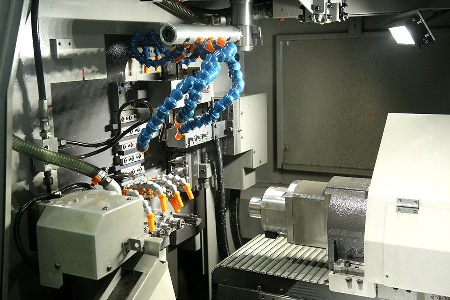
An optical waveguide housing looks like a simple milled block until you bore it, face the flange, and then it has to stay straight and flat after coating and a thermal cycle. CNC precision machining of a housing that holds its form is a controlled chain, not a quick cut. Here is how we run a waveguide program so it meets spec after it leaves the building.
Stage 1 - Material and roughing
- Certify the incoming stock with a mill certificate confirming the alloy (aluminum 6061/7075, stainless 304/316, or Invar 36 as the design dictates).
- Rough the pocket, bores, and flange lands with moderate feeds, leaving even stock so the part does not build residual stress that later relaxes and distorts the body.
- For long or thin benches, plan a stress-relief or natural-aging step before the finish pass so the housing does not warp after anodize or coating.
- Hold the part in a purpose-built fixture so every later operation references the same datum axis.
Stage 2 - 5-axis machining of the bores and flanges
- Bore and turn the optical passage first with sharp tooling and fine, consistent passes to protect roundness and concentricity.
- Face the flange square to the bore axis so the window or ferrule seats true.
- Drill and ream the bolt pattern with tight position control so the mating module locates repeatably.
- Form any integrated ribs, bosses, or wire channels in the same setup to protect datums.
Stage 3 - Finish, inspect, document
- Finish the contact faces to the target Ra, measured with a profilometer rather than judged by eye.
- Apply the surface treatment the design calls for (anodize, passivation to ASTM A967, or a hard coat) without disturbing geometry.
- Deburr every edge so no burr becomes a crack starter or a particle that later scatters your beam.
- Inspect critical features on a CMM and tie the lot to its material cert, machine log, and Certificate of Conformance.
The point is simple: a waveguide body only stays straight and flat if the process respected the material and the datum at every stage. A shop that skips stress relief or final verification is handing you a body that will warp or wander after it ships. Ask to see the process, not just the price.
Tight Tolerance CNC: Dimensional Control on Waveguide Bodies
Spend the tight tolerance where the beam path depends on it - nowhere else.
Tight tolerance CNC on a waveguide body is about priorities, not a single magic number. The flange flatness, the bore roundness, the alignment-feature position, and the body's flatness are the features that earn a tight callout. The cosmetic walls and the overall length do not. Specifying everything tight is the fastest way to inflate cost with zero benefit to the optical performance.
Typical tolerances we hold by feature
| Feature | Typical tolerance | Why it matters on a waveguide body |
|---|---|---|
| Flange flatness | 0.005 - 0.01 mm | Window or ferrule seats square; off-flat throws the beam off-axis. |
| Bolt-pattern position | +/- 0.02 - 0.05 mm | Mating module locates repeatably, beam path stays stable. |
| Bore diameter | +/- 0.005 mm | Optic or sleeve fit; sloppy here means play and drift. |
| Bore roundness | 0.005 mm | Even seat, even stress around the optical element. |
| Body flatness (datum) | 0.01 - 0.02 mm | Bench stays true against thermal and shock loads. |
| Overall length | +/- 0.1 mm | Envelope control; rarely functionally critical. |
We routinely hold +/- 0.005 mm on the critical bore and locating features of precision waveguide bodies where the application demands it, and we measure rather than trust. The number only means something because it is measured, recorded, and tied to the lot.
Pros
- Beam lands where the design says
- Repeatable module mating across a fleet
- Faster, cleaner optical qualification
- Fewer escapes, returns, and field failures
Cons
- Tight features cost more to hold
- CMM and flatness time grows with the callouts
- Not every feature needs them - only the ones the beam touches
The right answer from a vendor is specificity: which features are tight, why, and how each is checked. That honesty is a stronger qualification signal than any brochure claim about precision.

Optical CNC precision component
Optical CNC Parts: Lens Barrels and Mirror Bases That Hold Alignment
The barrel and the base are what keep the beam where you aimed it.
On an optical bench the lens barrel and the mirror base are the interfaces the beam trusts first. A barrel that is not bored concentric with its thread hands the lens an off-axis seat; a mirror base whose reference face is not flat and square hands the reflector an angle error that grows with distance. These are optical CNC parts in the truest sense - their geometry is the optical design, made physical.
Why alignment features belong in the optical conversation
- The lens must seat coaxial with the barrel thread, or the focus shifts off-axis.
- The bolt pattern decides whether the mating module seats square, with no preload on one side.
- A faced, flat flange removes the shim-and-hope step that hides alignment error in assembly.
- Traceable machining means every instrument in a fleet shares the same optical geometry.
| Alignment feature | What it protects | Target we hold |
|---|---|---|
| Flange squareness to bore | Beam coaxiality | 0.005 - 0.01 mm |
| Bolt-pattern position | Module seat repeatability | +/- 0.02 - 0.05 mm |
| Bore-to-flange concentricity | Optic runout | 0.005 - 0.01 mm TIR |
| Pilot / register diameter | Lens or sleeve location | +/- 0.005 mm |
| Surface finish on seat | No particle scatter, no galling | Ra 0.4 - 0.8 um, mirror on request |
We treat the lens barrel and mirror base as optical CNC parts interfaces because that is what they are. The same 5-axis setup, the same CMM proof, and the same batch record that protect a waveguide body protect your lens seat and your mirror angle. A barrel machined to a wish will hand your optical path an off-axis start every shot.
For the mating parts in that chain, our optical CNC parts technical guides cover lens barrels, mirror bases, and Invar benches where the same runout discipline continues downstream of the seat.
Waveguide Components vs Cast Housings: A Buyer's Comparison
The choice is rarely about which is 'better' - it is about what the part's first job is.
The most common fork buyers face is whether the body in hand should be a CNC-machined metal block - a functional, tightly toleranced, repairable member - or a cast housing that is cheaper per piece but harder to locate precisely and harder to rework. Neither is 'better' in the abstract; the right call depends on whether the part's first job is carrying a precisely located optical element or just enclosing a low-precision assembly.
| Factor | CNC waveguide components | Cast housings |
|---|---|---|
| Optical alignment precision | Bored, faced, reamed to +/- 0.02 mm | Molded datum, harder to hold tight alignment |
| Repairability | Re-machine a seat or a bore | Usually replace the whole casting |
| Stiffness per gram | Excellent in 7075-T6 or Invar | Good, but grain and porosity vary |
| Corrosion | Anodize or passivate handles it | Porosity can trap moisture and corrode |
| Cost at volume | Scales well with our 500k/mo floor | Lower piece cost at very high volume |
| Best use | Lens seats, mirror bases, fiber flanges | Enclosures, low-precision shells |
Choose machined waveguide components if
- The body carries a precisely located lens, mirror, or fiber port.
- You need a bored register or a tight bolt pattern for a mating module.
- Field repair and repeatability across a fleet matter.
- You want one supplier for the body, the seat, and the mating precision parts.
Choose cast housings if
- The shell is non-critical and pure enclosure is the only driver.
- The shape is a one-off you can mold once at very high volume.
- You accept bonded or pressed inserts rather than machined precision.
- Repeatability and field rework are not priorities.
Optical CNC precision component
Custom CNC Parts: Designing Waveguide Flanges and Alignment Features
Material is the first lever on stiffness, thermal stability, and corrosion.
Material is the first thing that decides whether your optical module holds alignment across temperature, survives a humid lab, or rusts in a month. Waveguide bodies usually balance three or four candidates, and the 'best' one is the one that meets your stiffness, thermal, and environment budget at the same time - not the one with the highest number on a data sheet.
Material decision for waveguide bodies
| Material | Behavior | Best use on a waveguide body |
|---|---|---|
| Aluminum 7075-T6 | High strength-to-weight, stable | Load-bearing benches, beam-delivery heads |
| Aluminum 6061 | Easy to machine, good corrosion resistance | General housings, fiber flanges |
| Stainless 304 / 316 | Heavy but corrosion proof | Humid labs, medical and food-adjacent optics |
| Invar 36 | Near-zero thermal expansion | Metrology, interferometer, and stability-critical benches |
| Copper (plated) | Thermal and EMI, soft | RF-adjacent waveguide, heat-path parts |
We machine all of these and will tell you when Invar 36's thermal stability is worth its cost and when 6061's machinability and corrosion resistance are enough. The honest answer is a stiffness-and-thermal trade, not a default - and it is the kind of call that should be made against your actual environment, not a catalog rule.
A short design-to-order flow
- Send the drawing, the optical path, the environment, and how the body is handled.
- We return a DFM note: which features need tight callouts and which are waste.
- Agree the material against your stiffness, thermal, and corrosion budget.
- Prototype first, measure flatness and concentricity, then lock the production process.
For the material and finish trade-offs across the parts we make, our custom CNC parts guides go deeper on aluminum, stainless, and Invar choices for optical hardware.
Stainless Steel Mirror Finishing for Optical Waveguide Surfaces
The finish is a function on an optical part, not a beauty pass.
Most waveguide bodies are aluminum and live in dry air, where anodize is enough. But medical, food-adjacent, and humid-laboratory optics, and any surface that sees moisture or must be wiped clean, need stainless and a passive, smooth surface. Stainless steel mirror finishing enters the story when the body must resist corrosion and wipe clean - and when a sealing or seating face must not gall on assembly.
Finish grades and where they belong on a waveguide body
| Finish grade | Typical Ra | Where it is used on a waveguide body |
|---|---|---|
| Standard machined | 0.8 um | Non-contact walls and cosmetic surfaces |
| Fine turned | 0.4 um | Reference diameters and light seats |
| Mirror (8K) | 0.2 um | The sealing or seating face that must not gall or scatter |
| Bead-blasted | 1.6 - 3.2 um | Non-critical faces prepared for bonding or coating |
- Ra
- Arithmetic average roughness; lower means smoother. Ra 0.2 um is our 8K mirror target.
- 8K finish
- A mirror-grade surface we reach at Ra 0.2 um, smooth enough to read as a near-perfect reflection.
- Passivation (ASTM A967)
- A chemical treatment that restores stainless chromium-oxide so it resists corrosion.
- Scatter
- Stray light bounced off a rough surface; a smooth face keeps it down.
Reaching a true mirror on stainless means controlled machining followed by careful leveling and verification with a profilometer. Pairing that with passivation to ASTM A967 gives you both the smooth, hard seat and the corrosion resistance a humid-laboratory or medical optical body sees against moisture, cleaning agents, or a field wipe-down.
Optical CNC precision component
A Buyer's Checklist for Sourcing Tight Tolerance CNC Waveguide Components
Copy this and send it to every shop on your shortlist. The answers sort them fast.
- Can they show a mill certificate confirming the alloy (6061 / 7075 / 304 / 316 / Invar 36) and grade?
- Do they stress-relieve or age bodies, or just cut them and hope they stay straight?
- Can they state a flange-flatness target and verify it with a CMM flatness map, not by eye?
- Will they hold and prove +/- 0.005 mm critical bore features with inspection records tied to the lot?
- Do they bore and ream the bolt pattern so the mating module seats repeatably across a fleet?
- Do they finish the seat to a measured Ra and anodize or passivate stainless to ASTM A967?
- Can they deburr and clean the body to your cleanliness and contamination spec?
- Do they provide first-article inspection, batch traceability, and a Certificate of Conformance on every lot?
- Are tolerances quoted against your drawing, with a DFM opinion on which ones actually matter?
A supplier that clears all nine is rare and worth keeping. One that stumbles on material certification, stress relief, flatness verification, or passivation should not be on a waveguide program - those are exactly the controls that keep a body aligned and a beam on target after it ships.
Common Mistakes Buyers Make When Specifying Waveguide Components
Most waveguide failures are decided at the drawing stage, not on the shop floor.
- Calling out 'smooth' instead of a real Ra target, then arguing about it after shipment.
- Tolerancing only the OD and forgetting flange flatness, so beam misalignment slips through.
- Skipping stress relief, so the body warps a few microns after anodize or coating.
- Tightening every dimension to save worry, inflating cost and lead time with no benefit to the beam.
- Ignoring bolt-pattern position, so the mating module seats cocked and the beam walks.
- Forgetting to ask how flatness will be proven - a number with no CMM map is a wish.
- Specifying exotic material when 6061 or 7075 meets the budget, paying weight you never use.
- Neglecting a burr-free, clean edge so a pristine body scatters light from a stray particle.
None of these are subtle, and all of them are avoidable at the sourcing stage. The disciplined supplier makes the right habit the easy default: ask for the environment, prove the flatness, anodize or passivate the metal, and tell you honestly when mirror finishing is overkill.
Optical CNC precision component
Optical CNC precision component
Optical CNC precision component
Optical CNC precision component
FAQ: waveguide components & Optical Buyer Questions
A: It is a precision-machined housing, bench, or flange that locates and protects the elements of an optical path - lenses, mirrors, fiber ports, detectors. In a laser cavity it seats the mirror and holds the bore the beam passes through; in a transceiver it aligns the ferrule. For waveguide components like these, the part only works if its flange stays flat and its bore stays concentric so the beam lands where you designed it.
A: We routinely hold flange flatness to 0.005 - 0.01 mm, bolt-pattern position to +/- 0.02 - 0.05 mm, and critical bore diameters to +/- 0.005 mm, all verified by CMM with records tied to the lot. The measured number is what your optical qualification accepts, not the drawing promise.
A: The barrel and base are the interfaces the beam trusts first. If the flange is not faced and located with optical-part discipline, the lens seats off-axis and the mirror sits at a wrong angle that grows with distance. We machine the barrel and base with the same 5-axis setup, CMM proof, and batch record we use for the waveguide body itself.
A: Aluminum 7075-T6 is the strength-to-weight, stable default for load-bearing benches; 6061 is the easy-to-machine, corrosion-resistant choice for general housings; stainless 304/316 wins in humid or medical labs; Invar 36 is the near-zero-expansion choice for metrology and stability-critical benches. The right call is a stiffness-and-thermal trade against your environment, not a default.
A: A mirror (8K) finish at Ra 0.2 um on a sealing or seating face reduces galling and keeps stray-light scatter down, and paired with passivation to ASTM A967 it resists corrosion from moisture, cleaning agents, or a field wipe-down. We leave the structural body with a functional finish; the finish is a function, not a beauty pass.
A: We hold ISO 9001 and have completed ISO 13485, and IATF 16949 is currently in application rather than certified - we are transparent about that. We are not AS9100 certified; we apply the documented traceability, first-article inspection, and SPC discipline of our ISO 9001 / ISO 13485 / IATF 16949 (in application) system, which maps to the expectations optical buyers ask about.
Designing a waveguide body that has to stay aligned, flat, and corrosion-resistant in your optical system? Send us your drawing and we will return a free DFM review with material, tolerance, finish, and passivation recommendations - an honest engineering answer, whether 6061, 7075, 304/316, or Invar 36 is right for your instrument.
Request a Free CNC Quote