CNC Waveguide Components: RF Tolerances for Communication Enclosures (2026 Guide)
As an RF engineer specifying a waveguide run, you have probably watched a perfectly good link budget collapse because a flange interface reflected a few percent of the power straight back at the source. The part looked fine on the CMM report - but at 10 GHz a 0.02 mm step at the seam is enough to wreck your VSWR. This guide is about the machining tolerances that actually decide whether your waveguide performs, or merely looks machined.
We will walk through how dimensional error becomes RF loss, the aluminum CNC machining workflow we use to hold those numbers, milled-versus-cast trade-offs for EMI shielding, connector machining for flanges, and how the tolerance budget for a waveguide body differs from a generic electronic housing. You will leave with comparison tables, a decision checklist, and the questions worth putting to any supplier before you release a purchase order.
LusterControl is a Dongguan source factory that has machined precision stainless and aluminum parts since 2015 - 60 CNC machines, a 4,000 sqm floor, and monthly output around 500k parts, certified to ISO 9001 with ISO 13485 completed and IATF 16949 in application. We are not an RF lab, but we machine the metal that comms OEMs and RF labs trust, so the trade-offs below are the ones we argue through with customers before the first chip is cut.
Table of Contents
- 1. How RF Tolerances Break a Waveguide: The Mechanics Behind Communication Enclosures
- 2. How We Machine Waveguide Walls: An Aluminum CNC Machining Workflow
- 3. Milled vs Cast Waveguide: Which Wins for EMI Shielding
- 4. Connector Machining for Waveguide Flanges and Adapter Fittings
- 5. Electronic Housings vs Waveguide Bodies: What the Tolerance Budget Changes
- 6. CNC Heat Sinks and Thermal Paths Inside RF Assemblies
- 7. RF Tolerance Comparison: Commercial vs Instrument-Grade Communication Enclosures
- 8. Choosing Aluminum CNC Machining vs Other Processes for Your Waveguide
- 9. Common Mistakes When Sourcing Communication Enclosures and Waveguide Parts
Electronics&Communication AI part image
How RF Tolerances Break a Waveguide: The Mechanics Behind Communication Enclosures
Dimensional error is RF error - just measured in decibels.
A rectangular waveguide is, at heart, a hollow metal pipe that guides microwaves by bouncing them down its walls. For a WR-90 section used across the 8.2-12.4 GHz X-band, the inner cross-section is a fixed 22.86 mm by 10.16 mm rectangle. Those two numbers are not decorative - they set the cutoff frequency and the characteristic impedance of the line. Machine the bore a few hundredths of a millimetre too wide or too narrow and you shift the impedance, reflect energy toward the source, and watch your link budget leak away as return loss.
Where dimensional error turns into RF loss
Three relationships decide whether your waveguide performs: the inner-wall dimensional accuracy on the a and b dimensions, the flatness and straightness of those same walls, and the seam where two milled halves or a flange pair meet. A continuous, predictable inner surface is what keeps the wave bouncing forward instead of scattering into heat and reflection.
- Inner a/b dimension held to +/-0.01 mm commercial, +/-0.005 mm instrument-grade
- Inner-wall surface finish Ra 0.4 micro m standard, Ra 0.2 micro m (8K mirror) on low-loss runs
- Flange seating face perpendicular to bore axis within 0.02 mm
- Seam step between mated halves kept below 0.01 mm to protect VSWR
The three-step chain from drawing to delivered power
Think of it as energy source, medium, result. Your transmitter is the energy source; the machined waveguide is the medium; delivered power at the antenna is the result. If the medium's walls deviate, the result is reflected power you never recover. The entire job of tight tolerance is to keep the medium invisible to the signal.
- VSWR (Voltage Standing Wave Ratio)
- The ratio of forward to reflected power at an interface; 1.0 is perfect, higher numbers mean more energy bouncing back toward the source.
- Characteristic impedance
- The intrinsic opposition a waveguide presents to the travelling wave, set largely by the a/b ratio of the bore.
- Insertion loss
- The decibels of power lost as the signal passes through the part, raised by rough walls and bad seams.
| Tolerance / finish | Controls | Fails as | Our standard |
|---|---|---|---|
| a/b inner dimension +/-0.005 mm | Characteristic impedance | Reflected power, detuned band | Held on 5-axis, CMM-verified |
| Inner-wall Ra 0.4-0.2 micro m | Skin-effect loss | Higher insertion loss | Standard Ra 0.4, 8K Ra 0.2 option |
| Flange perpendicularity 0.02 mm | Mate alignment, VSWR | Seam step, leakage | CMM first-article |
| Seam step <0.01 mm | Field continuity | EMI leakage at joint | Single-setup milling |
Electronics&Communication AI part image
How We Machine Waveguide Walls: An Aluminum CNC Machining Workflow
Single-setup 5-axis keeps the datum under the part for the whole run.
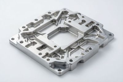
Most waveguide bodies we cut start life as 6061 or 7075 aluminum plate - light, conductive, and kind to tight tolerances. We pocket the bore first, then mill the outer profile and flange, frequently in one 3+2 setup so the inner walls and the flange faces share a single datum. Holding that datum through the whole run is what lets us promise the numbers in the table below.
Step 1 - Roughing and stress relief
Aluminum plate carries residual stress, and thin waveguide walls will move the moment you remove the bulk. We rough the bore, then let the part relax on the fixture before semi-finishing - skipping this step is the fastest way to a part that measures good warm and warps cold.
- Rough the bore and outer pocket with high material-removal passes
- Unclamp and let the blank relax for stress relief
- Semi-finish to leave 0.1-0.15 mm stock
- Finish inner walls with light engagement and sharp tools
- Verify on CMM plus a surface-finish scan
Step 2 - Finish pass for the inner walls
The finish pass is where the RF lives. We hold the inner dimension to +/-0.01 mm as a commercial baseline and push to +/-0.005 mm on instrument-grade runs, using low radial engagement (around 0.5 mm or 8 percent of cutter diameter) and sharp carbide so the walls stay true and the Ra stays low without a second operation.
Step 3 - Verify geometry and finish
Every first article goes on the CMM for a full datum report; batch parts get in-process gauging and lot-level audits. The inner-wall Ra is confirmed with a surface scanner, not guessed - because at X-band the difference between Ra 0.8 and Ra 0.2 micro m shows up directly in the insertion-loss measurement.
| Parameter | Commercial | Instrument-grade | Verified by |
|---|---|---|---|
| Inner a/b tolerance | +/-0.01 mm | +/-0.005 mm | CMM first-article |
| Inner-wall finish | Ra 0.4 micro m | Ra 0.2 micro m (8K) | Surface scan |
| Flange perpendicularity | 0.03 mm | 0.02 mm | CMM |
| Setup strategy | 3+2 single setup | 5-axis single setup | Datum-locked |
If your part sits alongside other precision work, our communication enclosures machining guides cover the tolerance decisions we walk through with comms OEMs.
Milled vs Cast Waveguide: Which Wins for EMI Shielding
EMI shielding lives or dies at the seam - and that is a machining problem.
When volume climbs, casting looks tempting - until you remember that EMI shielding lives or dies at the seam, and the seam is exactly where casting is hardest to control. A milled waveguide gives you one continuous inner surface and a flange face you can lap true; a cast one relies on a parting line and a coating to fake continuity.
Pros
- Continuous, predictable inner surface - no parting-line step
- Flange face and bore share a datum, so perpendicularity is real
- Low Ra straight off the machine, no secondary burnish needed
- Easy to hold +/-0.005 mm on the a/b dimension
Cons
- Higher piece price at very high volume
- Longer lead than a finished cast blank
- More material removed (but aluminum is cheap to machine)
| Factor | Milled (CNC) | Cast |
|---|---|---|
| Inner-wall step at seam | <0.01 mm (single setup) | 0.02-0.05 mm at parting line |
| Surface finish Ra | 0.2-0.4 micro m achievable | 1.6 micro m+, needs coating |
| Flange perpendicularity | 0.02 mm | 0.05-0.10 mm typical |
| Tooling / lead time | No hard tooling, 5-10 day proto | Tooling 4-8 wks, then fast |
| Best volume | 1 to ~5,000/yr | 5,000+/yr |
| EMI seam continuity | Excellent | Depends on coating |
The same seam-discipline question shows up in EMI shielding enclosure work, where we treat the joint as the part that actually does the shielding.
Electronics&Communication AI part image
Connector Machining for Waveguide Flanges and Adapter Fittings
The flange is where your return loss is won or lost.
The flange is where your return loss is won or lost. A cover flange (UG-type) or a choke flange only does its job if the seating face is flat, the bolt circle is true, and the pilot registers the bore concentric. We treat flange machining as the precision step of the whole job, not an afterthought bolted on at the end.
Flange perpendicularity and bolt-circle truth
- Pilot diameter to h7 fit with the mating boss
- Bolt-circle true position within +/-0.03 mm
- Seating-face flatness 0.02 mm over the whole face
- Seat Ra 0.8 micro m so the gasket or gasket-less joint bites
- Thread depth controlled on 4-40 or custom fixes
Adapters: rectangular bore to coax and circular
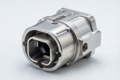
Adapter bodies need both waveguide tolerance on the rectangular end and connector machining on the coax end - a threaded, concentric seat for the SMA or N interface. Holding the two bores concentric to a few microns is what keeps the transition loss low. This is where our turn-mill and 5-axis cells earn their keep.
| Feature | Spec we hold | Why it matters |
|---|---|---|
| Seat flatness | 0.02 mm | Even gasket compression, no leak path |
| Bolt-circle true pos | +/-0.03 mm | Flanges seat without shimming |
| Pilot concentricity | 0.01 mm | Bore stays on axis |
| Coax thread seat | Concentric +/-0.01 mm | Low transition loss |
Electronic Housings vs Waveguide Bodies: What the Tolerance Budget Changes
A housing hides a tolerance; a waveguide cannot.
A generic electronic housing can hide a sloppy tolerance behind a cover; a waveguide body cannot, because every inner dimension is live RF. Understanding that difference is the fastest way to stop over-specifying the box and under-specifying the guide.
| Feature | Electronic housing | Waveguide body |
|---|---|---|
| Inner walls | Cosmetic, loose | RF-critical, +/-0.005 mm |
| Surface finish | As-machined fine | Ra 0.2-0.4 micro m for loss |
| Flange / seam | Gasket-dependent | Seam step <0.01 mm |
| Cost driver | Appearance, fit | Electrical performance |
When an enclosure becomes RF-critical
The moment you shield an enclosure for EMI - say a receiver front end - the seam stops being cosmetic and starts behaving like a waveguide joint. The lesson carries straight into the next section: shielding is a machining problem before it is a coating problem.
Electronics&Communication AI part image
CNC Heat Sinks and Thermal Paths Inside RF Assemblies
Power amplifiers get hot; the waveguide stays cold by design.
Waveguides themselves stay near ambient, but the power amplifier feeding them does not. RF assemblies often bolt a machined heat sink to the PA, and that fin stack is where lightweight CNC machining meets thermal reality. Getting it right keeps the amplifier in its linear region instead of thermal-foldback.
Fin geometry versus thermal resistance
Fins only help while air or conduction can reach the root. We optimise fin pitch, height, and wall thickness so the part does not warp during cutting and still moves heat. A 1.5 mm fin at 20 mm tall with 3 mm pitch is a common sweet spot for forced-air RF decks.
| Geometry | Effect | Trade-off |
|---|---|---|
| Taller fins | More surface, lower Rth | Warp risk, taller envelope |
| Tighter pitch | More area | Airflow choke if <2 mm |
| Thinner walls | Lighter, more fins | Springs during finish cut |
Browse our aluminum CNC machining resources for fin-stack DFM rules we hand to power-electronics customers.
RF Tolerance Comparison: Commercial vs Instrument-Grade Communication Enclosures
Pick the tier by the spec you must pass, not by habit.
Pick the tolerance tier by the spec you must pass, not by habit. Most test fixtures and prototypes are happy at commercial grade; production comms hardware that has to certify usually needs instrument-grade on the bore and flange.
| Parameter | Commercial | Instrument-grade | Our capability |
|---|---|---|---|
| Inner a/b tolerance | +/-0.01 mm | +/-0.005 mm | +/-0.005 mm held |
| Inner-wall Ra | 0.4-0.8 micro m | 0.2 micro m (8K) | Ra 0.2 micro m available |
| Flange perpendicularity | 0.03 mm | 0.02 mm | 0.02 mm CMM-verified |
| Seam step | <0.02 mm | <0.01 mm | <0.01 mm single-setup |
| First-article proof | CMM optional | CMM required | CMM always |
Choose commercial if / Choose instrument-grade if
- Commercial if: prototype, sub-6 GHz, non-certified internal link
- Commercial if: cost-driven high volume with margin in the spec
- Instrument-grade if: X/Ku-band, must certify VSWR, low-loss link
- Instrument-grade if: the flange seats a sensitive front end
- Confirm the band and required VSWR
- Decide commercial vs instrument-grade up front
- Agree Ra on inner walls (0.2 micro m for low loss)
- Spec flange perpendicularity and bolt-circle truth
- Ask for CMM first-article on instrument-grade
- Lock coated-vs-bare tolerance if anodizing
Electronics&Communication AI part image
Choosing Aluminum CNC Machining vs Other Processes for Your Waveguide
The right process is the cheapest one that still meets the true-position callout.
The right process is the cheapest one that still meets the true-position callout. For most waveguide work that is aluminum CNC machining, but there are edges where another route wins - and knowing the boundary saves real money at volume.
| Method | Best for | Watch out for |
|---|---|---|
| Aluminum CNC milling | 1-5,000/yr, tight bore + flange | Piece cost above very high volume |
| Die casting | >5,000/yr, loose RF | Parting-line step kills X-band |
| Electroforming | Complex irises, low volume | Slow, fragile walls |
| Extrusion + mill | Long straight runs | No complex bends |
Choose aluminum CNC machining if / Choose another process if
- Choose aluminum CNC if: you need +/-0.005 mm bore and a true flange now
- Choose aluminum CNC if: volumes under a few thousand a year
- Choose casting/extrusion if: volume is high and band is low-frequency
- Choose electroforming if: you need sub-mm irises a mill cannot reach
Talk to our team at Dongguan Licun Technology and we will quote each waveguide on the cheapest process that still meets your true-position callout.
Common Mistakes When Sourcing Communication Enclosures and Waveguide Parts
Most RF rejects trace back to one of these five habits.
Most RF rejects we see back from the field trace to one of five habits. None of them is exotic - they are the things that look fine on a casual drawing review and bite at certification.
- Specifying finish on the outer wall but leaving the inner bore 'as machined'
- Forgetting flange perpendicularity and blaming the gasket
- Treating a cast waveguide as RF-ready below 6 GHz without measuring
- Drawing tolerances on the bare part while planning to anodize
- Skipping the CMM first-article and trusting a photograph
- Ask for the cert stack: ISO 9001 minimum, ISO 13485 / IATF 16949 a plus
- Request material certs traceable to the heat lot
- Confirm single-setup 5-axis capability, not 3-axis with re-fixturing
- Get a CMM first-article report, not just a photograph
- Agree coated vs bare tolerances before quoting
- Verify batch traceability and a real rework path
Electronics&Communication AI part image
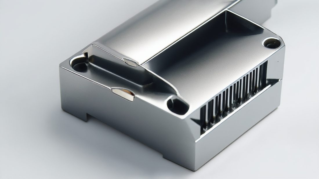
Electronics&Communication AI part image
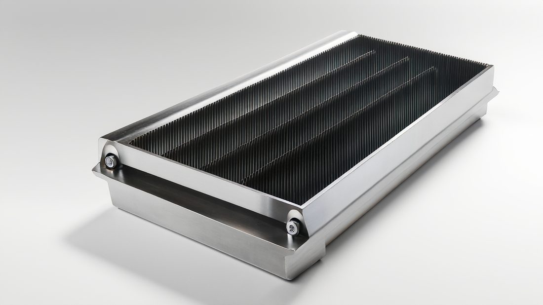
Electronics&Communication AI part image
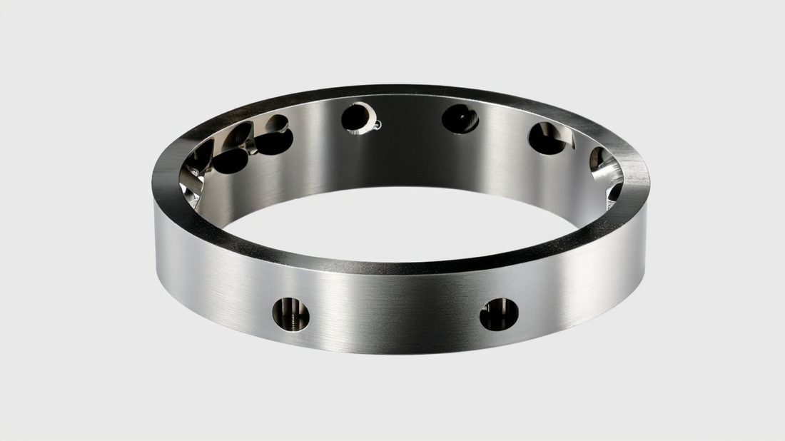
Electronics&Communication AI part image
FAQ: electronic housings & Electronics&Communication Buyer Questions
A: For an 8.2-12.4 GHz WR-90 section we hold the 22.86 x 10.16 mm inner dimensions to +/-0.01 mm commercial and +/-0.005 mm instrument-grade, with flange perpendicularity 0.02 mm. If your spec must certify VSWR at X-band, go instrument-grade on the bore and flange rather than betting on commercial.
A: Yes. Skin-effect loss scales with wall roughness; we see a measurable insertion-loss delta between Ra 0.8 micro m and Ra 0.2 micro m (8K) on X-band runs. We hold Ra 0.4 micro m standard and offer the 8K Ra 0.2 micro m finish on low-loss links.
A: Mill it. At 10 GHz the parting-line step and rougher walls of a cast body silently raise insertion loss and weaken EMI shielding. Casting only makes sense below about 6 GHz or at very high volume where you can afford a secondary burnish.
A: Single-setup 5-axis milling keeps the bore and flange on one datum, so perpendicularity stays at 0.02 mm and the seam step stays below 0.01 mm. Every first article is CMM-verified; batch parts get in-process gauging and lot audits.
A: Often yes. Our turn-mill and 5-axis cells hold the rectangular bore and the SMA/N coax seat concentric within a few microns in a single setup, keeping transition loss low. Send the assembly drawing and we will confirm the setup.
A: We are ISO 9001 certified, ISO 13485 completed, and IATF 16949 in application; material certs trace to the heat lot, first articles get a full CMM datum report, and every bar is traced to the finished waveguide. ASTM A967 passivation is available on exposed aluminum.
Send us your waveguide or communication-enclosure drawing for a free DFM review. We will flag the features that should move to 5-axis, the tolerances that are quietly costing you yield, and the cheapest process - milled aluminum or otherwise - that still meets your true-position callout. Reach out and let's cut the first article.
Request a Free CNC Quote