CNC Worm Shaft Machining: Tolerances and Lead Accuracy (2026 Guide)
If your gearbox hums, heats up, or develops backlash after a few thousand cycles, the culprit is rarely the motor. More often it is the worm shaft — the long, threaded cylinder that converts rotation into smooth, self-locking reduction. When its lead accuracy drifts by a few microns, the wheel it drives eats itself at the contact line, and the whole drive starts to complain.
This 2026 guide walks you through how worm shafts are actually cut on a CNC shop floor, what tolerances matter versus which ones are cosmetic, and how to read a drawing so you can tell a capable supplier from a cheap one before you commit. We write it the way an engineer would brief a buyer: with the numbers that protect your yield, not the adjectives that pad a brochure.
You will leave with a sourcing checklist, three comparison tables, and a clear answer to the question every actuator designer faces: worm shafts, spline shafts, or precision gears — which one belongs in your assembly?
Table of Contents
- 1. Worm Shafts 101: What Lead Accuracy Means for Your Gearbox
- 2. Turn-Mill Compound Machining of Worm Shafts and Precision Gears
- 3. CNC Gear Machining Workflow: Cutting the Worm and the Wheel
- 4. Spline Shaft vs Worm Shafts: Which Drives Your Actuator?
- 5. Coupling Machining Tolerances That Protect Worm Shafts Alignment
- 6. Precision Gears and Worm Shafts: A Surface Finish Comparison
- 7. How to Read a Worm Shafts Drawing: Tolerances Buyers Must Verify
- 8. Buyer's Checklist: Sourcing Turn-Mill Compound Worm Shafts
- 9. Common Mistakes When Specifying CNC Gear Machining Tolerances
Precision Transmission AI part image
Worm Shafts 101: What Lead Accuracy Means for Your Gearbox
Before you spec a tolerance, you have to know which number on the drawing actually moves the needle.
- Worm shaft
- A cylinder cut with a helical thread (the worm) that meshes with a worm wheel to give high-ratio speed reduction with self-locking capability.
- Lead
- The axial distance the thread advances in one full 360° turn. It sets the reduction ratio together with the wheel tooth count.
- Lead angle
- The helix angle of the thread; small lead angles (under ~5°) create the self-locking effect most gearboxes rely on.
- Lead accuracy
- How closely the actual lead matches the designed lead along the full thread length. It is the single biggest driver of uniform backlash.
Think of lead accuracy as the thread's straightness in the axial direction. If the lead is off by 0.01 mm per turn, the worm contacts the wheel on one flank only. That concentrates load on a few teeth, raises local temperature, and within weeks you hear the whine that means the lubricant film has broken down. At LusterControl we hold worm threads to ±0.005 mm on turned diameters and treat lead variation as a first-class inspection item, not a nice-to-have.
Why Lead Accuracy Decides Backlash
Backlash is the slack between worm and wheel when you reverse direction. A well-cut worm with tight lead accuracy gives you predictable, repeatable backlash you can design around. A poorly cut one gives you backlash that changes with position — so your servo has to hunt, your positioning drifts, and your encoder starts lying to you. For medical device components and robotic joints where repeatability is the product, this is not a detail; it is the spec.
Precision Transmission AI part image
Turn-Mill Compound Machining of Worm Shafts and Precision Gears
One workpiece, one setup, one datum chain — that is why turn-mill wins for shafts.
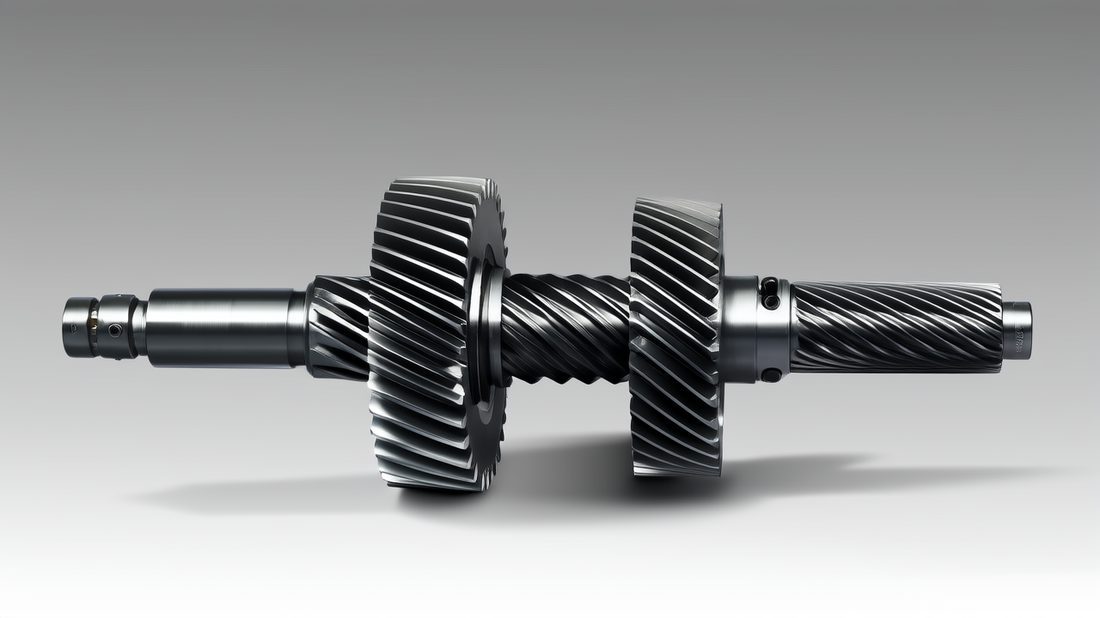
A worm shaft is not just a thread. It is a shaft with bearing journals, a thread section, maybe a keyway or a coupling shoulder, and two end faces that must stay concentric to the thread axis. Turning those features on one machine and then moving the part to a second machine to cut the thread is where datums get lost. Turn-mill compound machining does it all in a single chucking, so the thread and the journals share one coordinate system.
Step 1: Bar Stock to Rough Profile
We start from certified stainless or alloy bar (303, 304, 17-4PH, or 416 for wear resistance) and rough the journals and shoulders on the main spindle while the counter-spindle supports the free end. Roughing leaves 0.15–0.25 mm for finish passes so heat from cutting does not lock in distortion. For high-volume runs our Swiss-type sliding-headstock machines hold the bar steady within microns while the tools move.
Step 2: Thread Hobbing the Worm
The worm thread is generated by a synchronized milling or hobbing pass, not by a single-point tool chasing the part. Synchronization between the C-axis (part rotation) and the thread cutter keeps the lead constant along the full length. We verify lead on a gear-measuring routine after the first piece and again at the midpoint of the batch, because tool wear is the enemy of lead accuracy on long worms.
Step 3: Mirror Finishing and Inspection
For seals and for worm wheels that run dry or near-dry, we push the thread root and bearing surfaces to a mirror finish — standard Ra ≤ 0.6 µm, up to 8K mirror at Ra 0.2 µm after electropolish. Every worm shaft ships with a first-article report and a lot-traceable material certificate. You can see how we structure these workflows alongside our other technical guides on precision gears and spline shafts.
| Factor | Turn-mill compound (one setup) | Lathe + separate hob (two setups) |
|---|---|---|
| Datum chain | Single, thread & journals shared | Broken between machines, stacked error |
| Lead accuracy typical | ±0.005 mm achievable | ±0.01–0.02 mm, setup-dependent |
| Concentricity journal-to-thread | ≤ 0.008 mm | ≤ 0.02 mm |
| Setup time per batch | Lower (no re-chuck) | Higher (re-fixturing) |
| Best for | Shafts with thread + journals | Simple worms, low mix |
CNC Gear Machining Workflow: Cutting the Worm and the Wheel
The worm and its wheel are a matched pair — cut them on different discipline levels and the pair fails early.
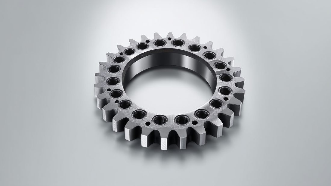
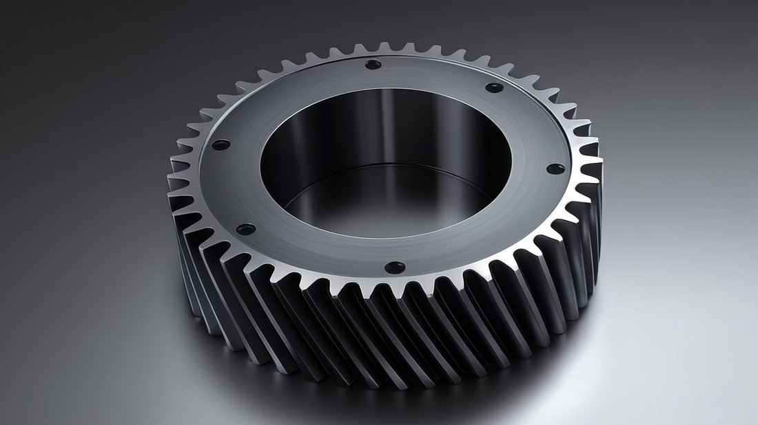
A worm reduction set is only as good as the worst of its two parts. CNC gear machining for the wheel uses a different toolpath logic than the worm thread, but the two must share the same lead and module or they bind. We cut wheels on 5-axis and turn-mill centers, then pair-test a sample worm-and-wheel for contact pattern before releasing the batch.
| Attribute | Worm (shaft thread) | Worm wheel (gear) |
|---|---|---|
| Driving feature | Helical thread, continuous | Concave teeth, indexed |
| Key tolerance | Lead accuracy ±0.005 mm | Tooth thickness ±0.01 mm |
| Finish driver | Sealing / friction at root | Contact pattern uniformity |
| Inspection | Lead + pitch + runout | Tooth scan + composite test |
| Typical material | 416 / 17-4PH stainless | Bronze (C932) or phosph-bronze |
Bronze wheels against stainless worms are the classic combination: the softer wheel wears instead of the worm, so you replace the cheap part, not the expensive one. But the stainless worm still needs the right hardness and a clean, low-Ra thread so it does not gall the bronze. That is why we tie the worm finish spec to the wheel material you choose.
Precision Transmission AI part image
Spline Shaft vs Worm Shafts: Which Drives Your Actuator?
They solve different problems. Picking on price instead of function is the usual mistake.
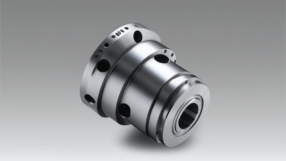
A spline shaft transmits torque through meshing ridges and is great when you need high torque density and the ability to slide axially (think telescoping drives). Worm shafts trade torque density for reduction ratio and self-locking. If your actuator must hold position when the power is off, a worm wins. If it must push hard in a compact envelope and slide, a spline shaft is often the answer.
| Need | Worm shafts | Spline shaft |
|---|---|---|
| High reduction in one stage | Yes (10:1 to 60:1+) | No (needs gearing) |
| Self-locking when off | Yes (low lead angle) | No |
| Sliding axial motion | No | Yes |
| Torque per size | Moderate | High |
| Efficiency | 40–85% | 90%+ |
Choose Spline Shaft If
- Your drive slides axially during operation (telescoping or indexing).
- You need maximum torque in a small diameter and can add a brake for holding.
- Efficiency and heat matter more than self-locking.
Choose Worm Shafts If
- The load must stay put with no power (hoists, valve actuators, medical tilts).
- You want a big ratio in one compact stage without extra gears.
- Backlash repeatability beats raw efficiency in your spec.
Coupling Machining Tolerances That Protect Worm Shafts Alignment
The best worm is useless if the coupling that joins it to the motor is cut loose.
Coupling machining sounds trivial until you realize the coupling is what keeps the worm shaft coaxial with the motor shaft. A coupling bored 0.02 mm oversize, or with faces that are not square to the bore, introduces angular misalignment that the worm thread amplifies into uneven wheel wear. We bore couplings on the same turn-mill envelope that cuts the worm, so the two share a process discipline.
| Feature | Loose spec (fails) | Tight spec we hold |
|---|---|---|
| Bore diameter | H8 (+0.04) | H7 / ±0.005 mm |
| Bore-to-face squareness | 0.05 mm | ≤ 0.01 mm |
| Keyway symmetry | ±0.05 | ±0.015 |
| Surface on seal seat | Ra 1.6 µm | Ra 0.6 µm |
| Balance class | none | G6.3 typical |
For servo-driven worm sets we also offer a light electropolish on the coupling bore seat so it slips onto the motor shaft without galling. It is a small step that removes a common assembly-line swear word. Misalignment you cannot see at install time shows up as a warm gearbox at 2,000 hours — exactly when warranty claims arrive.
Precision Transmission AI part image
Precision Gears and Worm Shafts: A Surface Finish Comparison
Finish is not polish-for-show. On a worm it is the difference between a quiet life and a warranty claim.
- Ra (roughness average)
- Arithmetic mean of surface peaks and valleys in micrometres. Lower Ra = smoother.
- 8K mirror finish
- Our top tier, Ra 0.2 µm, produced by machining plus electropolish; looks and performs like a ground surface.
- Electropolish
- An electrochemical pass that levels micro-peaks and also meets ASTM A967 passivation for stainless corrosion resistance.
| Finish tier | Ra | Where we use it | Process |
|---|---|---|---|
| As-machined | 1.6 µm | Non-contact structural shafts | CNC turn |
| Standard mirror | ≤ 0.6 µm | Bearing journals, couplings | Fine turn + light polish |
| 8K mirror | 0.2 µm | Worm thread roots, seals, medical | Turn + electropolish (ASTM A967) |
For a worm that meshes with a bronze wheel, an 8K mirror on the thread root drops friction and lets the lubricant film form evenly. That is why our medical and semiconductor-grade worm shafts ship at Ra 0.2 µm. The same electropolish that smooths the part also passivates it to ASTM A967 — one operation, two wins, and a certificate you can hand to your quality team.
How to Read a Worm Shafts Drawing: Tolerances Buyers Must Verify
Most worm rejects trace back to a drawing that buried the one tolerance that mattered.
When you send a drawing to a shop, you are really sending a contract. The tolerances you call out tell the machinist where to spend time and money. We have seen worm shafts quoted three ways for the same function because the drawing left the lead tolerance unstated. Before you release an RFQ, confirm these items are on the print — and if you want a second set of eyes, send us your drawing for a free DFM review.
| Drawing element | What to verify | Why it matters |
|---|---|---|
| Lead / pitch | Explicit value + tolerance (±0.005 mm) | Drives backlash and ratio |
| Thread form | Spec (e.g., ZA/ZN/ZI/ZK) | Must match wheel hob |
| Journal diameters | Tolerance + datum reference | Bearing fit, runout |
| Material & heat treat | Grade + hardness band | Wear, galling, corrosion |
| Finish callouts | Ra per surface, not 'polished' | Friction, sealing, life |
- Lead and pitch stated with a numeric tolerance, not 'as standard'.
- Thread form and hand (LH/RH) called out explicitly.
- Each journal references a single datum axis (A-B).
- Material certificate and heat-treat band required on the PO.
- Ra value on every functional surface, including the thread root.
Precision Transmission AI part image
Buyer's Checklist: Sourcing Turn-Mill Compound Worm Shafts
Five questions separate a partner who protects your yield from a vendor who ships and forgets.
Sourcing from Dongguan Licun Technology or any shop, the same rules apply. Before you award the job, ask for evidence, not promises. The items below are what our own inbound quality team checks on every receiving inspection — and what you should demand from your supplier.
- First-article report (FAI) with lead, pitch, and runout measured, not estimated.
- Material certificate (mill cert) traceable to the exact lot.
- Process capability data (Cpk) on the worm thread if you run high volume.
- Finish proof: surface-test report showing Ra on the thread root.
- Rework and deviation policy in writing — who pays if the lead is out?
Common Mistakes When Specifying CNC Gear Machining Tolerances
These five errors show up in most rejected RFQs. Avoid them and your quote comes back sane.
Tight tolerances cost money only where they earn it. The art of a good drawing is putting the tight number where function lives and relaxing it everywhere else. Here is where buyers routinely go wrong on worm shafts and precision gears.
- Calling out ±0.005 mm on a non-functional decorative shoulder — it inflates cost and lead time for nothing.
- Leaving lead tolerance blank and assuming 'shop standard' — there is no such thing across vendors.
- Specifying Ra 0.2 µm on a surface that never contacts anything; spend it on the thread root instead.
- Mixing a left-hand worm with a wheel hobbed for right-hand; the pair will not mesh.
- Forgetting the datum chain, so journals and thread are inspected against different axes.
Hold the tight number where the mesh lives, and relax it everywhere else — that is how a worm shaft stays affordable and accurate at the same time.
Precision Transmission AI part image
Precision Transmission AI part image
Precision Transmission AI part image
Precision Transmission AI part image
FAQ: worm shafts & Precision Transmission Buyer Questions
A: For most industrial and robotic worm sets, hold lead variation within ±0.005 mm and pitch within a similar band. Tighter than that rarely buys quietness but always buys cost. The bigger lever is a matched worm-and-wheel roll test, which catches lead error a CMM on the worm alone will miss.
A: Choose worm shafts. A low lead angle (under about 5°) gives the self-locking that holds position with no power — ideal for hoists, valve actuators, and medical tilt mechanisms. A spline shaft transmits more torque in less space but will not hold position without a brake, so it is the wrong pick when 'stays put when off' is the requirement.
A: The worm thread root is where the bronze wheel contacts and where lubrication film forms. At Ra 0.2 µm (our 8K mirror tier, produced with electropolish that also meets ASTM A967 passivation) friction drops and wear evens out. A rough root concentrates load, heats the wheel, and shortens life — finish here is function, not looks.
A: Require a first-article report with measured lead, pitch, and runout; a mill material certificate tied to the lot; a surface-test report proving Ra on the thread root; and, for high volume, Cpk data on the thread. Also ask for a worm-and-wheel roll (contact-pattern) test. At LusterControl these ship standard with every batch.
A: Yes — turn-mill compound machining cuts the journals, shoulders, and worm thread in a single chucking, so they share one datum axis and the lead stays tied to the bearings. That is why we run worms on turn-mill and Swiss-type centers rather than moving the part between a lathe and a separate hob.
A: For medical device components look for ISO 13485 (we have completed it) on top of ISO 9001. For automotive-tier work, IATF 16949 is the bar — we are currently in application. Always pair the certificate with lot-level material traceability and a first-article report; the cert alone does not prove the specific part is in control.
Sending a worm shaft or precision gear set to quote? Send us your drawing for a free DFM review — we will flag the tolerances that actually protect your backlash and tell you where you can safely relax the print to save cost.
Request a Free CNC Quote