CNC Worm Shaft Machining: Tolerances for Energy Storage (2026 Guide)
If you are designing or sourcing an energy storage system (ESS) cabinet, a battery-swap station, or a telecom backup enclosure, chances are you have a motion problem you did not expect: you need a compact actuator that holds position with no power, survives vibration and corrosion, and never back-drives into a dangerous state. A worm shaft is often the quietest answer to that problem, yet most procurement teams spec it from a catalog and hope the shop gets the geometry right.
This guide walks through how a worm shaft is actually produced on a CNC floor, what the tolerance numbers on your drawing really control, and where these parts sit inside an energy storage assembly. We write it from the buyer's and the engineer's seat at the same time: what you should ask your supplier, and why the answer changes with the application. By the end you should be able to read a worm-shaft drawing, judge a supplier's capability, and hand off a spec that will not come back as scrap.
Everything below is grounded in how Dongguan Licun Technology (brand LusterControl) actually runs stainless and aluminum worm-shaft work on our 60+ CNC floor in Dongguan, China, not in generic textbook claims. Where a number matters, we give you the number.
Table of Contents
- 1. Why Worm Shafts Matter in Energy Storage Systems
- 2. How CNC Precision Machining Shapes a Worm Shaft
- 3. Tight Tolerance CNC: Lead Accuracy and Tooth Geometry
- 4. Energy Storage CNC Parts: Where Worm Shafts Sit in the Assembly
- 5. Stainless Steel Mirror Finishing for Corrosion-Prone Housings
- 6. Custom CNC Parts: When Standard Worm Shafts Don't Fit
- 7. Worm Shafts vs Spur Gears: A Self-Locking Comparison
- 8. Common Mistakes When Specifying Tight Tolerance CNC Worm Shafts
- 9. A Buyer's Checklist for Energy Storage CNC Parts
Energy Storage CNC precision component
Why Worm Shafts Matter in Energy Storage Systems
A worm shaft is the helical screw that meshes with a worm wheel to turn rotation 90 degrees and multiply torque in one compact stage.
An energy storage enclosure is a hostile, crowded box. You have batteries, busbars, cooling loops, and control gear packed into a cabinet that may sit outdoors in coastal humidity or on a telecom tower in the desert. Any moving part inside it needs to be small, quiet, and fail-safe. A worm shaft delivers exactly that: a single mesh between the worm and its wheel gives reduction ratios of 20:1 to 60:1 in one stage, transfers motion at 90 degrees, and is self-locking when the lead angle is shallow enough that the wheel cannot drive the worm backward.
Self-locking is the property that makes worm gearing attractive for safety-critical ESS motion. A battery-swap latch, a coolant isolation valve, or a fire-suppression damper must stay put when the motor is de-energized. A spur or bevel gear train will back-drive under load; a correctly specced worm will not. You get a mechanical brake without a brake.
Where you actually find worm-shaft actuation in ESS
- Battery-swap robot end-effectors: the gripper that locks and releases a module carriage, holding torque while the robot decelerates.
- Coolant and refrigerant valve positioners: small rotary actuators that meter flow in a liquid-cooling plate loop.
- Cabinet latch and interlock levers: door and compartment locks that must remain engaged through shock and vibration.
- Busbar isolation levers: manual or motorized disconnects where position must be unambiguous and non-back-driving.
- Fire-suppression and ventilation dampers: dampers that hold open or closed without continuous power.
The trade-off is efficiency. Worm meshes run at 40-90 percent efficiency depending on lead angle and finish, losing more to sliding friction than rolling gears. For low-duty ESS actuation that is a fair price for self-locking and packaging density. For high-cycle servo axes, you would choose differently, and we cover that comparison later.
Energy Storage CNC precision component
How CNC Precision Machining Shapes a Worm Shaft
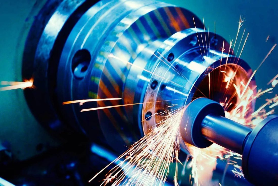
A worm shaft is not one operation; it is a sequence where each stage controls a different property of the finished part.
We machine worm shafts as a three-stage flow. The first stage controls geometry and material integrity, the second controls the thread itself, and the third controls the surface and fit. Understanding the sequence tells you which line item on a supplier's quote maps to which property you care about.
Stage 1: blank, turn, and turn-mill the shaft body
The shaft starts as bar stock (303/304/316L stainless, 17-4PH, or 6061/7075 aluminum for weight-sensitive UAV and portable ESS). A Swiss-type automatic lathe or a turn-mill compound center turns the journal diameters, shoulders, keyways, and the worm-gear-adjacent features in one clamping. Machining the worm and its bearing journals in a single setup is what lets us hold concentricity between the thread runout and the shaft axis.
Stage 2: cut the worm thread (lead accuracy lives here)
The worm flank is generated by hobbing or by single-point threading on a CNC turning center. The lead (axial advance per revolution) and the lead angle are set here, and any error in the lead is what produces backlash and noise downstream. We hold the worm to DIN 3975 / AGMA 6022 lead classes and verify lead with a lead-check or a CMM helix scan, not by eye.
Stage 3: finish, heat treat, and passivate
After threading, the part may be hardened (for steel worms) and then ground or polished to the target flank finish. For corrosive ESS environments we apply electrolytic or mirror polishing and LusterControl follows ASTM A967 passivation on stainless so the surface resists pitting. The finish you choose here is what decides running noise, wear life, and cleanability.
Tight Tolerance CNC: Lead Accuracy and Tooth Geometry
The three numbers that decide whether a worm shaft runs quiet and accurate are lead error, lead angle, and flank finish.
A worm is defined by its lead (how far it advances per turn), its lead angle (the helix angle at the pitch line), and its flank profile (trapezoidal per DIN 3975, or involute for some fine-pitch designs). Tight tolerance CNC work is what keeps these consistent part to part.
- Lead error
- Deviation of the actual axial advance from the nominal lead. Accumulated lead error is the main source of position drift and uneven backlash across a worm wheel.
- Lead angle
- The helix angle at the worm pitch diameter. Shallow angles (under ~5 degrees) are self-locking but lower efficiency; steeper angles raise efficiency but can back-drive.
- Backlash
- The slack between worm and wheel at the mesh. Too much = sloppy position; too little = binding and heat. It is set by flank offset and lead tolerance together.
- Envelope mesh
- A single-envelope worm is ground to wrap the wheel; a double-envelope (globoid) wraps both. More contact area, smoother load, harder to machine.
The tolerances we hold and what they buy you
| Parameter | Typical ESS spec | What it controls |
|---|---|---|
| Shaft diameter / journal | +/-0.005 mm | Bearing fit, runout, concentricity to worm thread |
| Lead accuracy | Class 7e-8e (DIN 3975) | Position repeatability, backlash uniformity |
| Worm flank finish | Ra 0.6 to 0.2 um | Running noise, wear life, lubrication film |
| Thread runout vs axis | < 0.01 mm TIR | Smooth mesh, no cyclic vibration |
| Heat-treat hardness (steel) | 28-45 HRC as required | Wear resistance vs. machinability trade-off |
For most energy storage actuators, the worm runs at low speed and low duty, so lead class 8e with a Ra 0.6 flank is plenty. If your actuator must hold a valve position to fine resolution or run near-silently in a residential or indoor cabinet, step to 7e lead and a mirror-finished flank near Ra 0.2 um. Mirror finishing is a standard capability at LusterControl: our baseline mirror is Ra 0.6 um, and our 8K process reaches Ra 0.2 um for the smoothest, cleanest flanks.
The honest read on tight tolerance CNC is that the drawing is only as good as the verification behind it. A supplier who cannot show you a lead-check report or a CMM helix scan is asking you to trust a number they did not measure. For CNC precision machining guides across our other energy storage components, see the related blog library.
Energy Storage CNC precision component
Energy Storage CNC Parts: Where Worm Shafts Sit in the Assembly
Mapping the worm shaft to its real job in the cabinet tells you which properties to prioritize.
An ESS cabinet is a system, and the worm shaft is rarely the hero part. It is the small, invisible component that makes a safety or comfort function work. Specifying it well means matching the duty to the mesh. Below is the application map we use internally when a customer sends a vague 'actuator shaft' request.
| Application in ESS | Duty | Why a worm fits | Our typical spec |
|---|---|---|---|
| Battery-swap gripper lock | Low cycle, hold torque | Self-locking under shock | 416/17-4PH, Ra 0.6 um, lead 8e |
| Coolant valve positioner | Moderate cycle, quiet | Compact 90 deg, fine position | 316L, mirror Ra 0.2 um, ASTM A967 |
| Cabinet interlock latch | Rare cycle, fail-safe | Holds with no power | 303 SS, Ra 0.6 um, hardened |
| Busbar isolator lever | Manual/rare, unambiguous | No back-drive to live parts | Brass or 304, RoHS finish |
| Fire damper actuator | Very low cycle, silent | Stay-put, corrosion-proof | 316L, passivated, Ra 0.6 um |
Notice the material and finish change with the environment, not with the geometry. A worm that lives inside a sealed, climate-controlled cabinet can be a simple 303 stainless part. One exposed to coastal air on a telecom site should be 316L with mirror finishing and ASTM A967 passivation to resist crevice corrosion at the thread root, where fluids pool. We treat energy storage components as an environment-driven spec, not a one-size part.
Stainless Steel Mirror Finishing for Corrosion-Prone Housings
In energy storage, the finish is part of the corrosion strategy, not just cosmetics.
Stainless steel mirror finishing is a LusterControl specialty and it matters more than people expect for energy storage. A mirror flank (Ra 0.6 um baseline, down to Ra 0.2 um at 8K) has fewer micro-crevices where moisture and contaminants collect. Pair it with electrolytic polishing and ASTM A967 citric or nitric passivation and you get a surface that resists pitting and is easy to wipe clean during maintenance.
When mirror finishing pays for itself
- Outdoor or coastal ESS where salt spray reaches the actuator.
- Food-adjacent or cleanroom-adjacent storage where wipe-down hygiene matters.
- Low-noise indoor cabinets (residential, office, telecom closet) where flank finish sets the sound floor.
- Applications where lubricant must film evenly and not pool in a rough flank.
| Finish tier | Roughness | Best for |
|---|---|---|
| Standard machined | Ra 1.6 um | Sealed, dry, indoor low-cycle |
| Fine machined | Ra 0.8 um | General ESS actuators |
| Mirror (baseline) | Ra 0.6 um | Corrosive or quiet environments |
| 8K mirror | Ra 0.2 um | Coastal, clean-critical, silent |
We have run mirror and electrolytic finishing for appliance-grade customers such as De'Longhi, Donlim, and Breville, where surface cleanliness and appearance are audited at incoming inspection. That same discipline transfers directly to energy storage parts that must survive field conditions rather than a showroom.
Energy Storage CNC precision component
Custom CNC Parts: When Standard Worm Shafts Don't Fit
Catalog worms are a starting point; real ESS assemblies usually need something non-standard.
Off-the-shelf worm shafts come in fixed leads, diameters, and materials. In a dense ESS cabinet, the odds are low that a standard part drops in. This is where custom CNC parts earn their keep: you define the lead, the journal features, the material, and the finish as one integrated component instead of bolting several catalog pieces together.
Common customizations we machine
- Non-standard lead or lead angle to hit a specific reduction and self-lock threshold.
- Integrated features: the worm and a bearing shoulder, encoder flat, or hex on one shaft.
- Hollow worm shafts to cut rotating mass in portable or drone-carried ESS.
- Mixed-material builds: stainless worm on an aluminum or steel adapter.
- Sealed or IP-rated versions with O-ring grooves for washdown environments.
Turn-mill compound machining is the enabler: because we can turn, drill, mill, and thread in one clamping, an integrated worm shaft is cheaper to make correctly than the equivalent stack of separate components, and it is inherently more accurate. If your drawing currently shows a worm plus two spacers plus a collar, ask whether it should be one part.
Worm Shafts vs Spur Gears: A Self-Locking Comparison
The right comparison is not 'which gear is best' but 'which property does your ESS function require'.
Engineers often default to spur gears because they are cheap and efficient. For ESS safety motion, that default can be wrong. The table below contrasts the three mesh types you would realistically choose between for cabinet actuation.
| Property | Worm shaft + wheel | Spur gear pair | Bevel gear pair |
|---|---|---|---|
| Self-locking | Yes (shallow lead) | No | No |
| Reduction per stage | 20:1 to 60:1 | Up to ~5:1 | Up to ~4:1 |
| Efficiency | 40-90% | 95-98% | 90-95% |
| Noise | Low (smooth slide) | Higher (mesh click) | Medium |
| Axial thrust | High (needs thrust bearing) | None | Moderate |
| Package size | Compact, 90 deg | Bulkier, parallel | Compact, 90 deg |
Pros
- Self-locking holds position with zero power, the key ESS safety property.
- High reduction in one stage keeps the actuator small.
- Quiet sliding mesh suits indoor and residential cabinets.
Cons
- Lower efficiency means more motor torque and heat to manage.
- Axial thrust needs a thrust bearing in the design.
- Harder to machine to fine lead classes than a spur gear.
Choose a worm shaft if / choose a spur gear if
- Choose a worm shaft if the motion must hold position with no power, needs a high reduction in a small box, or sits in a quiet indoor space.
- Choose a spur gear if the axis runs continuously at high speed, efficiency dominates, and a brake or servo hold handles the 'stay put' requirement.
- Choose a bevel pair if you need 90-degree transfer with high efficiency and can supply an external lock.
Energy Storage CNC precision component
Common Mistakes When Specifying Tight Tolerance CNC Worm Shafts
Most worm-shaft scrap comes from the drawing, not the machine. Here is what to fix before you send it.
We review a lot of incoming worm-shaft drawings, and the same avoidable errors repeat. Catching them at the spec stage saves a prototype loop and a month of lead time.
- Underspecifying the lead class: writing 'worm, 2 mm lead' with no class leaves lead error to chance and guarantees uneven backlash.
- Ignoring backlash direction: specifying a flank offset without saying which side binds the wheel produces a part that fits but jams.
- Wrong material for the environment: a 303 part in a coastal cabinet will pit at the thread root no matter how tight the tolerance.
- Skipping passivation on stainless: machining disrupts the oxide layer; without ASTM A967 passivation corrosion starts at the cut.
- No DFM review: a designer specifies a 0.3 mm web between the worm and a shoulder that cannot be deburred, so the part cannot be cleaned.
- Over-specifying mirror finish: Ra 0.2 um on a sealed dry cabinet wastes tolerance budget that should go to lead accuracy.
The fix is a short, specific drawing note block: material and grade, lead and class (e.g., 2 mm lead, DIN 3975 class 8e), flank finish (Ra 0.6 or 0.2 um), heat treat if any, passivation per ASTM A967, and required inspection report. That one block turns a vague request into a repeatable part.
A Buyer's Checklist for Energy Storage CNC Parts
Before you release a worm-shaft PO, run this seven-point check against your supplier and your drawing.
This is the practical close: a checklist you can paste into a sourcing email. If a supplier stumbles on more than one item, that is your signal to keep looking. LusterControl, as a Dongguan source factory with ISO 9001 certification, completed ISO 13485, and IATF 16949 in application, is built to clear every line below.
- Drawing states lead, lead class (DIN 3975 / AGMA 6022), and lead angle explicitly.
- Material grade and finish tier are named, with passivation per ASTM A967 for all stainless.
- Tolerance budget is on journals and runout (e.g., +/-0.005 mm), not just overall length.
- Environment rating is given (indoor / outdoor / coastal / IP) so material and finish match duty.
- Supplier offers lot-level material and process traceability from incoming bar to finished part.
- First-article (FAI / CMM helix scan) is included, not quoted as an extra surprise.
- A realistic lead-time and a DFM review are on the table before tooling, not after first scrap.
A supplier who answers this checklist without hesitation is one you can put on a qualified vendor list. If you want a second opinion on a drawing you already have, send your drawing for a free DFM review and we will flag the lead-class and passivation gaps before they cost you a build.
Energy Storage CNC precision component

Energy Storage CNC precision component
Energy Storage CNC precision component
Energy Storage CNC precision component
FAQ: worm shafts & Energy Storage Buyer Questions
A: On our floor we hold worm-shaft journal diameters and bearing seats to +/-0.005 mm, with thread runout to the axis under 0.01 mm TIR. Lead accuracy is held to DIN 3975 / AGMA 6022 class 7e-8e depending on the application. Tighter is possible but should be justified by the actuator's performance need, not specified by default.
A: A worm mesh is self-locking when its lead angle is shallow enough that the wheel cannot drive the worm backward. For ESS actuators such as battery-swap latches, coolant valves, and fire dampers, self-locking means the part holds position with no power and no brake, which is exactly the fail-safe behavior safety reviews want. Steeper lead angles raise efficiency but can back-drive, so the choice is a design decision, not an afterthought.
A: For coastal or outdoor ESS, choose 316L with mirror finishing and ASTM A967 passivation. The 316L resists pitting, the mirror flank (Ra 0.2 to 0.6 um) removes micro-crevices where moisture collects, and passivation rebuilds the chromium oxide layer cut during machining. A 303 or 304 part may be fine in a sealed indoor cabinet but will pit at the thread root in salt air.
A: Mirror finishing (Ra 0.6 um baseline, down to Ra 0.2 um at 8K) gives a flank with fewer valleys, so lubricant films evenly, wear is lower, running noise drops, and the surface is easier to wipe clean during maintenance. In low-noise indoor or clean-critical ESS cabinets that difference is audible and measurable, not cosmetic.
A: Choose custom when a standard lead, diameter, or material does not fit your cabinet, or when you can consolidate a worm plus spacers and collars into one integrated turn-mill part. Integration removes assembly steps and concentricity risks. At LusterControl we routinely merge a worm thread, bearing seat, and sensor flat into a single clamping for exactly this reason.
A: Require a first-article report that includes a lead check or CMM helix scan, flank finish measurement (Ra), journal and runout dimensions, hardness if heat-treated, and material and passivation certificates. If a supplier cannot provide a lead-class verification, they did not measure the property that controls your backlash, and you are accepting risk blindly.
Designing a worm-shaft actuator for your energy storage system? Send us your drawing and duty profile for a free DFM review, and we will flag the lead-class, material, and passivation gaps before they cost you a build.
Request a Free CNC Quote