FSW vs Deep-Groove Milling for Cold Plate Channel Machining (2026 Guide)
You approved a cold plate drawing that looked perfect on screen, then lost three weeks in thermal validation: junction temperature drifted, the pump curve looked fine, and nobody could explain why. In our experience the culprit is rarely the coolant. It is the channel — a sealing face that bowed after joining, burrs left in a deep pocket, or a surface finish that quietly changed the flow. If you are choosing between friction-stir welding (FSW) and deep-groove milling for liquid cooling plates and channels, that decision is where the outcome is decided.
This guide is written for the engineer or buyer who has to sign off on that decision. We compare the two routes on the things you can actually put in an RFQ: flatness after joining, channel roughness, leak tightness, inspection evidence, lead time, and cost at prototype versus production volume. No marketing adjectives — just the numbers we hold on our own floor and the questions you should ask any supplier.
We are LusterControl (Dongguan Licun Technology Co., Ltd.), a Dongguan source factory with 15 years of CNC stainless mirror machining, 60 CNC machines, a 4,000 m² plant and monthly capacity of 500,000 pieces. We run turn-mill composite, 5-axis, Swiss-type turning, mirror and electropolishing. This is the comparison we would give you across the table, not a brochure.
Table of Contents
- 1. Why Liquid Cooling Plates and Channels Decide Your AI Server Thermal Margin
- 2. How FSW and Deep-Groove Milling Work in Liquid Cooling Plate Machining
- 3. FSW vs Deep-Groove Milling: 7 Hard-Spec Factors for Cold Plate Channel Machining
- 4. High-Flatness Flow-Channel Control: What Actually Moves Your Datum
- 5. Tight Tolerance CNC: Sealing and Leak-Rate Evidence You Can Audit
- 6. CNC Precision Machining: From Your CAD File to First Article in Six Steps
- 7. Which Route for Your Liquid Cooling Plates and Channels? A Decision Matrix
- 8. Buyer's Checklist and Red Flags for Liquid Cooling Plate Machining
- 9. Common Mistakes in Cold Plate Channel Machining and How to Avoid Them
- 10. High-Flatness Flow-Channel Control: Materials, Passivation and the 2026 Standards List
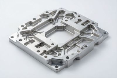
Liquid Cooling (Cold Plate) CNC precision component
Why Liquid Cooling Plates and Channels Decide Your AI Server Thermal Margin
Before you compare processes, get clear on what the part actually has to do.
A cold plate is a metal plate with an internal or semi-open network of channels through which coolant flows. Your heat source — a GPU package, a power module, a CDU interface — is clamped to the plate, heat crosses the contact interface, then moves into the coolant and out of the rack. The plate is not a passive slab: its flatness sets the thickness of your thermal interface material (TIM) layer, its channel geometry sets pressure drop, and its sealing integrity sets whether the rack stays up.
The thermal path, in three moves
Energy source: a heat flux measured in tens of watts per square centimetre on the device. Medium: a stainless or aluminium plate with machined passages and a coolant such as deionized water or glycol mix. Result: heat leaves the junction within the margin your thermal model assumed — but only if the machined surfaces match that model. Every micron of extra TIM gap and every burr that narrows a passage eats into the assumption.
The three failures buyers actually see
- Flatness loss after joining: the plate bows, the TIM layer thickens unevenly, and hotspot temperature rises even though the pump and flow rate did not change.
- Debris in the channel: milling burrs or weld flash break loose, collect at a manifold or micro-fin, and raise pressure drop over the first weeks of operation.
- Seal leakage at the cover: the unit passes a bench check, then weeps at temperature cycling. Downtime in a rack costs more than the part many times over.
This is why we start every cold plate conversation at the drawing, not at the price. You can browse more of our liquid cooling plates and channels engineering notes for the inspection side of the story; this article is about choosing the manufacturing route that makes those numbers repeatable.
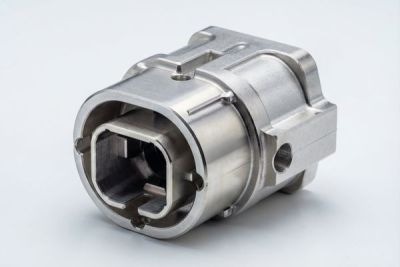
Liquid Cooling (Cold Plate) CNC precision component
How FSW and Deep-Groove Milling Work in Liquid Cooling Plate Machining
Two ways to make a sealed passage — one joins solid-state, one cuts the passage and then closes it.
Both routes start with a plate and end with a coolant-tight passage. They differ in when the passage is created and how it is closed. Understanding that difference tells you which tolerances are achievable and which ones will drift after assembly.
Route A: friction-stir welding, in three moves
- 1. A rotating tool plunges into the joint line between a grooved base plate and a cover plate. Frictional heat softens the metal without melting it — this is a solid-state weld, so there is no filler wire and no molten pool to shrink.
- 2. The tool shoulder forges the softened material as it travels. The seam is produced below the surface, with low heat input and therefore less thermal distortion than fusion welding or brazing.
- 3. We finish-machine the sealing face and datum features after the join. That last step is the one buyers forget to specify: post-join finishing is what turns a good weld into a flat, sealable surface.
Route B: deep-groove milling, in three moves
- 1. We rough out the channel pocket with a rigid 3-axis or 5-axis setup, leaving stock on the walls and floor for the finishing pass.
- 2. Smaller tools finish the channel walls and floor to the specified roughness — on a demanding CDU part, Ra 0.8 um or better — followed by manual or automated deburring so no chip remains in the passage.
- 3. The passage is closed: either by an integral machined design with a bolted manifold, or by joining a cover through brazing, fusion welding or a gasketed joint. The closing method, not the milling itself, usually decides the final flatness and leak performance.
- FSW (friction-stir welding)
- A solid-state joining process that uses a rotating tool to plasticize and forge metal along a seam without melting it. Lower distortion and no filler, but the seam path must be accessible to the tool.
- Deep-groove milling
- CNC material removal that cuts a channel deeper than it is wide into a solid plate, then closes it with a cover, manifold or second plate. Geometrically flexible, but the closing step adds a leak path.
- Flatness
- The maximum deviation of a surface from a perfect plane, normally called out on the mating face. On cold plates it controls the TIM gap and therefore thermal resistance.
- Ra (arithmetic roughness)
- The average height variation of a surface profile in micrometres. Lower Ra on a channel floor reduces fouling and pressure loss; on a sealing face it helps the gasket conform.
FSW vs Deep-Groove Milling: 7 Hard-Spec Factors for Cold Plate Channel Machining
Bring this table to your supplier review — it separates what each route can hold from what it only promises.
| Factor | FSW route | Deep-groove milling route |
|---|---|---|
| Sealing mechanism | Continuous solid-state seam, no filler metal; leak path limited to the weld line | Cover brazed, welded or gasketed after milling; leak path follows the entire perimeter |
| Flatness after joining | Low heat input, less distortion; sealing face finished after the weld to the drawing datum | Brazing or fusion closing adds thermal bow; post-join finishing is mandatory for high-flatness work |
| Dimensional capability | Sealing features held to +/-0.005 mm on stainless parts after finishing | Channel and datum features held to +/-0.005 mm when fixtured and inspected in one setup |
| Channel surface | As-milled passage before joining; deburring and cleaning critical before the cover goes on | Direct control of floor and wall finish; typical AI-server target Ra 0.8 um or better |
| Leak-rate evidence | Weld seam can be pressure-decay tested; typical spec below 0.01 mL/min at stated test conditions | Joint plus seam tested together; acceptance must state medium, pressure, dwell and limit |
| Geometry freedom | Tool access limits turns and internal features; best for straight or gently curved paths | Handles compact serpentine paths, stepovers and multi-depth passages |
| Volume and cost profile | Tooling cost up front, economical in repeat production with stable cycle time | Lower entry cost at prototype and small batches; machine time scales with channel length |
The seven factors, one by one
1. Sealing. If your rack cannot tolerate weeping at a fitting, ask how the passage is closed and what test proves it. A solid-state seam removes filler and porosity from the equation; a brazed or gasketed lid shifts the risk to the perimeter joint. Neither is automatically better — but one is easier to qualify when the geometry allows it.
2. Flatness. This is usually the deciding factor for AI-server cold plates. A warped mating face changes the TIM layer and your thermal model stops matching reality. Whatever route you pick, require flatness to be measured after the final joining and finishing operation, not on the bare plate before it.
3. Tolerance. On stainless mirror-finished parts we hold +/-0.005 mm. That number is only meaningful with a first-article CMM report tied to your datums. If a supplier quotes tight tolerance without naming the inspection tool, you are buying a promise, not a measurement.
4. Surface finish. For the coolant path, a spec such as Ra 0.8 um is a practical target for a CDU cold plate; our standard mirror finish is Ra 0.6 um or better, and our best 8K mirror reaches Ra 0.2 um. On a sealing land, finish helps the gasket conform; inside the channel, it influences fouling and pressure drop over months of operation.
5. Leak rate. 'Leak-free' is not a specification. A real requirement states test medium, pressure, dwell time, temperature and an acceptance limit such as below 0.01 mL/min. Ask for the calibration record of the test rig as well as the result.
6. Geometry. FSW needs a tool path. Deep-groove milling needs tool reach and careful chip evacuation. If your channel turns sharply or changes depth, milling gives you options the weld tool does not; if it is a long straight run, welding can be faster and more repeatable in volume.
7. Cost. At five pieces, machine time dominates, so milling usually wins. At five thousand, cycle time and scrap rate dominate, so the route with the more stable process wins — even if its tooling cost was higher at the start. Price per plate without a volume band is not a comparable number.
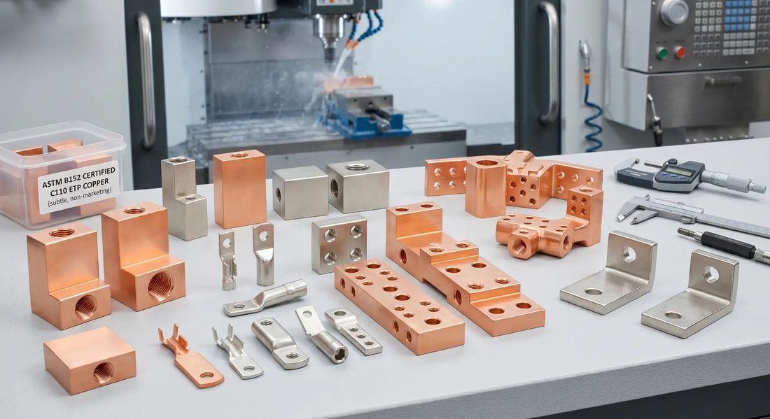
Liquid Cooling (Cold Plate) CNC precision component
High-Flatness Flow-Channel Control: What Actually Moves Your Datum
Flatness is not a property of the material. It is a result of the process sequence.
When you specify high-flatness flow-channel control, you are specifying a behaviour through heat and clamping, not a number on a raw plate. Residual stress from roughing, heat introduced by joining, and clamping force during final machining all move the datum. The shop that controls these in sequence will hit your CMM report; the shop that checks flatness only at incoming inspection will not.
Where flatness is won
- Stress management before finishing: rough, allow the blank to relax, then take the finishing pass so the material moves before it is measured, not after.
- Joining sequence control: for FSW, finish the sealing face after the weld; for a brazed or welded cover, measure the bow and machine the mating face last.
- Repeatable fixturing: locate from the same datums you call out on the drawing, so inspection and machining agree with the assembly.
| Spec item | What we hold at LusterControl | How you verify it |
|---|---|---|
| Dimensional tolerance on precision features | +/-0.005 mm on stainless mirror-finished parts | First-article CMM report referenced to your datums |
| Standard mirror finish | Ra 0.6 um or better | Surface profiler trace on a representative coupon or part |
| Best available mirror finish | 8K mirror, Ra 0.2 um | Profiler record plus visual acceptance standard |
| Channel roughness target (AI-server CDU spec) | Ra 0.8 um or better where specified | Profile trace inside the passage or on a machined witness sample |
| Flatness of mating face | Machined after joining, measured on the finished part | CMM flatness callout on the final inspection sheet |
Flatness is not inspected into a part. It is sequenced into a part.
Tight Tolerance CNC: Sealing and Leak-Rate Evidence You Can Audit
A leak number without a test method is just a wish with a decimal point.
Tight tolerance CNC matters most where the plate meets the coolant. Two methods dominate production: pressure decay, where you pressurize the passage and watch the drop over a defined dwell, and helium mass-spectrometer testing for very small leak limits. Neither method means anything until you state the medium, pressure, dwell, temperature and acceptance limit. A target such as below 0.01 mL/min is common on AI-server CDU cold plates; make it a contractual line, not an email assumption.
- Leak rate
- The quantity of gas or liquid escaping a sealed passage per unit time under a stated pressure and temperature. Always paired with the test method that produced it.
- Pressure decay
- A leak test that charges the part to a set pressure, isolates it, and measures the pressure drop across a defined dwell time.
- MTR (material test report)
- Mill documentation confirming the alloy and mechanical properties of the stock. EN 10204 3.1 is the commonly requested form when a project calls for it.
An audit-ready inspection chain
- 1. Incoming: verify material certificate and lot identity against the purchase order before the blank enters the machine.
- 2. First article: CMM the critical features and the mating-face flatness, and keep the report with the job record.
- 3. In process: check channel depth and critical widths at defined intervals so drift is caught before a full batch is committed.
- 4. Final: leak test plus surface and dimensional checks on the finished, joined plate — not on a pre-assembly sub-part.
- 5. Traceability: tie each shipping lot back to material, machine and inspection record, so a field issue can be narrowed to a batch.
| Evidence to request | What it proves | When to ask |
|---|---|---|
| First-article CMM report | Your datums were machined and measured, not assumed | Before the first production shipment |
| Leak-test procedure and result sheet | Method, limits and measured values for every tested unit | At qualification and in each lot |
| Material certificate (MTR) | The alloy matches the print and the corrosion spec | At incoming and with the delivery pack |
| Passivation record (e.g. ASTM A967) | Stainless surfaces were chemically treated to a stated standard | When the fluid or cleanliness spec requires it |
| Lot traceability record | Field issues can be isolated to a batch and a process step | For any program with field service obligations |

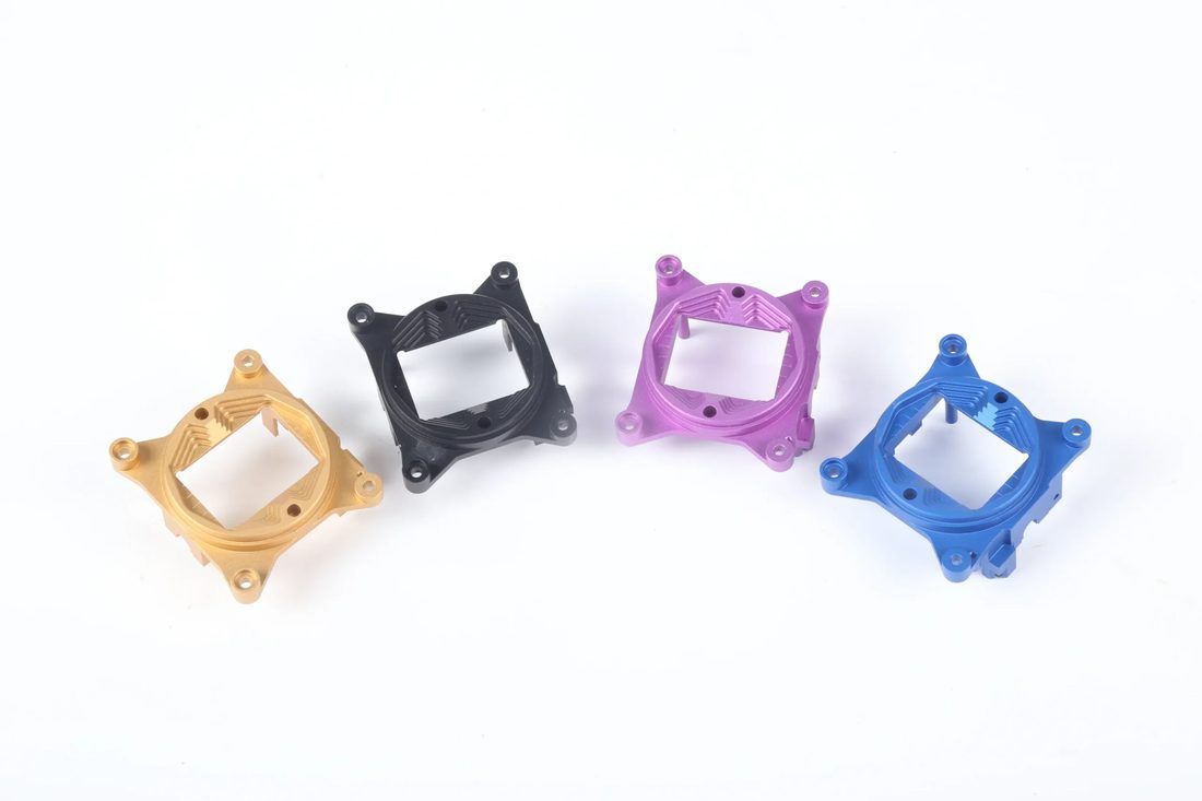
Liquid Cooling (Cold Plate) CNC precision component
CNC Precision Machining: From Your CAD File to First Article in Six Steps
What a disciplined shop does between the RFQ and the first good part.
CNC precision machining on a cold plate is a chain of decisions, not a single operation. Our job is to make the chain boring — the same datums, the same inspection points, the same result on piece one and piece five thousand. Here is the sequence we run, and where you should be involved.
- 1. DFM review: we read your 3D model and 2D drawing together, flag deep pockets with poor tool access, asymmetric walls that may move under clamping, and sealing lands without a flatness callout. This is the cheapest stage to change anything.
- 2. Material and blank selection: stainless or aluminium per your fluid and corrosion requirement; we confirm the MTR before release.
- 3. Stress-managed roughing: material comes off in controlled passes, with allowance left for finishing.
- 4. Finishing: channel walls and floor to the roughness spec, datum and sealing faces to the drawing tolerance, using 3-axis, 5-axis or turn-mill setups as the geometry demands.
- 5. Joining and post-join machining: FSW seam or covered channel, followed by final machining of the mating face so flatness is measured on the part you will actually assemble.
- 6. Inspection and release: CMM first article, leak test, deburr and clean, lot record, then packing that protects the sealing face in transit.
You can send your drawing for a free DFM review and we will tell you which of those steps needs attention on your specific part — including when the simpler process is the better answer.
Which Route for Your Liquid Cooling Plates and Channels? A Decision Matrix
Match the route to the requirement, not to the supplier's favourite machine.
Use this matrix as a first filter. If two rows point in different directions, bring the conflict to the DFM review — that is exactly the conversation that saves a rework loop later.
| Your project requirement | Recommended route | Why it wins |
|---|---|---|
| Straight or gently curved channel, stable repeat volume | FSW with post-join face machining | Low-distortion seam and short cycle time once tooling is proven |
| Serpentine path, stepovers, multiple depths or tight entries | Deep-groove milling | Tool path freedom; geometry does not have to suit a welding head |
| Prototype quantities or frequent design changes | Deep-groove milling | No dedicated weld tooling; changes are a program edit, not a new fixture |
| Highest flatness on a large mating face | Whichever route permits final machining after joining | Flatness is set by the last cut, not by the first one |
| Very low leak limit with fluid under temperature cycling | Route with the fewest perimeter joints, validated by a written test method | Fewer joints mean fewer places for a leak to start |
| Small-batch customization alongside eventual mass production | One shop that can run both | Process learning transfers instead of restarting at the volume supplier |
Put plainly, here is how we frame it with customers:
Pros
- Choose FSW if your channel is tool-accessible, your volume is stable, and low distortion plus a short repeat cycle matter more than geometric freedom.
- Choose FSW if your leak requirement is demanding and you want a continuous seam without filler metal.
- Choose FSW if you can commit to post-join machining of the sealing face in the same process plan.
Cons
- Choose deep-groove milling if your path turns tightly, changes depth, or needs features a welding tool cannot reach.
- Choose deep-groove milling if you are at prototype stage or expect design revisions before freeze.
- Choose deep-groove milling if your quantity is small enough that dedicated joining tooling will not pay back.
Either way, the decision should be made with someone who can run both routes and is not paid more for one. We are a Dongguan source factory supporting small-batch customization and volume production under one roof, so our recommendation does not depend on keeping a particular machine busy.
Liquid Cooling (Cold Plate) CNC precision component
Buyer's Checklist and Red Flags for Liquid Cooling Plate Machining
Five things to demand before you release a purchase order.
A buyer's checklist is not bureaucracy; it is the difference between a part that passes incoming inspection and a programme that slips. These are the items we would want in your RFQ pack if we were sitting on your side of the table.
- A 3D model and a 2D drawing that agree — datums, flatness callout on the mating face, and channel roughness all stated.
- A written leak requirement: test medium, pressure, dwell, temperature and acceptance limit (for example below 0.01 mL/min at stated conditions).
- First-article inspection deliverable, specifically a CMM report referenced to your datums.
- Material cert and lot traceability, with the passivation standard (such as ASTM A967) named if the fluid requires it.
- A capacity and lead-time curve by volume band, so a prototype price is not mistaken for a production price.
- Confirmation of when flatness is measured: after joining and final machining, not before.
- An NDA and controlled access to your CAD files if the design is proprietary.
Red flags that predict a late programme
- The supplier quotes from the 3D file only and never asks about datums or joining sequence.
- Every tolerance is 'no problem' with no inspection method attached.
- Flatness is certified on the raw plate, before the cover is joined.
- No deburr or cleaning step is described for the channel — debris will show up in your manifold.
- The price is identical at 10 pieces and 10,000 pieces, which usually means nobody costed the process.
Common Mistakes in Cold Plate Channel Machining and How to Avoid Them
The failure modes we see most often, and the fix for each.
| Mistake | Symptom you see | Fix |
|---|---|---|
| Specifying channel depth but not floor roughness | Pressure drop climbs over weeks as the passage fouls | Call out Ra (for example 0.8 um or better) and how it will be measured |
| Joining the cover after final machining | Sealing face bows; TIM gap grows; hotspot appears | Machine the mating face after joining and re-measure flatness |
| Deburring as an afterthought | Debris at manifold or micro-fin, intermittent flow restriction | Define deburr and clean as a process step with sign-off |
| Using 'leak-free' as the acceptance criterion | Dispute at incoming inspection over test method | Write method, pressure, dwell and limit into the drawing |
| Buying prototype and production from different shops | Sample works, volume parts drift, qualification must be repeated | Keep one process owner from sample to release |
The hidden-cost trap
A lower unit price can disappear quickly when you add incoming rework, a second qualification round, or a thermal margin that quietly shrank because the mating face moved. When you compare quotes, compare the inspection deliverables and the number of times the part is handled after joining. Those two lines explain most of the price difference that is not material cost.
Liquid Cooling (Cold Plate) CNC precision component
High-Flatness Flow-Channel Control: Materials, Passivation and the 2026 Standards List
The paperwork is part of the part. Here is what to name in your next RFQ.
For coolant-side components, stainless steel is often chosen for corrosion resistance and cleanliness. That choice brings obligations: the passivation treatment, the material certificate, and the surface finish all need to be stated, not assumed. Our standard mirror finish is Ra 0.6 um or better and our best 8K mirror reaches Ra 0.2 um — useful when a sealing face or a cleanable surface benefits from a smoother finish, though the channel itself is usually specified to a more practical target such as Ra 0.8 um.
- ASTM A967
- A standard specification for chemical passivation treatments for stainless steel parts. Naming it in your RFQ makes the treatment verifiable instead of descriptive.
- Electropolishing
- An electrochemical finishing process that removes a thin surface layer, reducing roughness and improving cleanability on stainless parts.
The standards checklist for your RFQ
- ISO 9001: our certification (25025Q13824R0S) is current to 2028-12-02 and underpins document control and inspection records.
- ISO 13485: our aligned quality system is established and certification is in progress — ask for the current status rather than accepting an outdated claim.
- IATF 16949: in application; relevant if your cold plate crosses into automotive or power-electronics supply chains.
- ASTM A967: name it when stainless passivation is required by the fluid or cleanliness spec.
- EN 10204 3.1: request when project rules call for a certified material test report.
Standards do not make a flat plate by themselves; a disciplined sequence does. But they let you audit the claim. That is the whole point of this guide: pick the process that fits your geometry and volume, then demand the evidence that proves the part you receive matches the part you modelled. If you want to see where else we apply that approach, start at LusterControl and work backward from the inspection pack.
Liquid Cooling (Cold Plate) CNC precision component
Liquid Cooling (Cold Plate) CNC precision component
Liquid Cooling (Cold Plate) CNC precision component
FAQ: liquid cooling plates and channels & Liquid Cooling (Cold Plate) Buyer Questions
A: Start with the test conditions, not just a number: state the medium, pressure, dwell time, temperature and acceptance limit. A typical CDU cold plate target is below 0.01 mL/min, but that figure is meaningless unless both sides agree on the method. Ask your supplier for the written procedure and the calibration record of the test rig.
A: No. FSW offers a low-distortion, filler-free seam and good repeatability for tool-accessible paths, but tight turns and multi-depth passages may be impossible for the welding tool. Deep-groove milling gives greater geometry freedom and lower entry cost at prototype volumes. Choose by geometry, volume and flatness requirement.
A: We hold +/-0.005 mm on stainless mirror-finished precision features. On a cold plate, the question is when that tolerance is measured: require a first-article CMM report on the mating face after joining and final machining, referenced to the datums on your drawing.
A: Because roughness affects fouling and pressure drop over the service life, and finish on the sealing land affects gasket conformity. For AI-server CDU channels, a target of Ra 0.8 um or better is common. Our standard mirror finish is Ra 0.6 um or better, with 8K mirror at Ra 0.2 um where a smoother surface is justified.
A: Send the 3D model and 2D drawing together, plus material, annual volume and volume bands, channel roughness and flatness callouts, and your leak-test requirement. If the design is proprietary, tell us and we will put an NDA in place before you share the CAD files.
A: Yes, and it is usually cheaper in the long run. LusterControl runs 60 CNC machines in a 4,000 m2 Dongguan plant with monthly capacity of 500,000 pieces, so a part can stay with one process team from first sample through volume release instead of being requalified at a second factory.
Send us your cold plate drawing for a free DFM review. We will tell you whether FSW or deep-groove milling fits your geometry, volume and flatness target — and what evidence you should require before release.
Request a Free CNC Quote