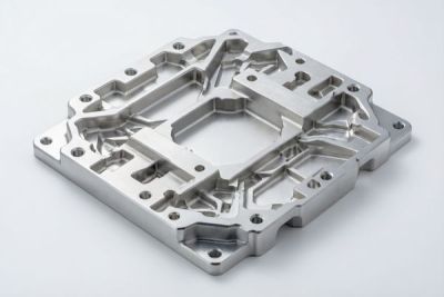
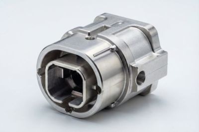
Gas Distribution Plates: Controlling 200+ Micro-Hole Consistency (2026 Guide)
If you are building a plasma etcher, a CVD chamber, or a gas-delivery manifold, the gas distribution plate - often called a showerhead - is the single part that decides whether your process runs uniform or quietly scrapes a whole wafer lot. The geometry looks trivial: a flat plate with a few hundred through-holes. The hard part is that every one of those 200+ holes has to pass the same flow, within a band tight enough that no spot on the substrate sees a different gas mix than its neighbor.
The trap is invisible. A 5 micron drift in hole diameter, a burr you cannot see under a loupe, or a rough internal channel can shift local flow by more than 10 percent. Multiply that across a 300 mm wafer and you get non-uniform deposition that shows up only as yield loss weeks later. This guide walks you through what actually controls micro-hole consistency, which process fits your geometry, what tolerances and finishes really matter, and a checklist you can hand to any supplier before you release a PO.
We machine these parts at our Dongguan source factory - LusterControl, Dongguan Licun Technology Co., Ltd. - where 60 CNC machines and mirror finishing down to Ra 0.2 micrometer let us hold the kind of consistency a semiconductor tool needs. Everything below is written so you can verify it yourself, not so we can brag.
Table of Contents
- 1. What Makes Gas Distribution Plates and Fluid Blocks Hard to Machine?
- 2. Why Gas Distribution Plate Precision Machining Starts with Burr-Free Holes
- 3. How Turn-Mill Composite Processing Keeps 200+ Holes Aligned
- 4. Tight Tolerance CNC: Holding ±0.005 mm Across the Plate
- 5. Precision Fluid Block Machining: Flow Uniformity and Surface Finish
- 6. CNC Precision Machining vs EDM for Micro-Hole Arrays
- 7. Buyer's Checklist: Sourcing Gas Distribution Plates and Fluid Blocks
- 8. Common Failures in Gas Distribution Plate Precision Machining
Semiconductor Equipment (Gas / Fluid) CNC precision component
What Makes Gas Distribution Plates and Fluid Blocks Hard to Machine?
The shape is simple. The tolerance stack is not.
A gas distribution plate is a sealing face with a uniform array of micro-holes that meters process gas into a chamber. A precision fluid block is the same idea turned sideways: internal channels and drilled ports that route gas or liquid with no leaks and no turbulence. On paper both are just drilled plates. In practice you are stacking hole position, hole diameter, edge break, internal roughness, and flatness against each other - and a miss in any one of them shows up as flow variation.
- Gas distribution plate
- A perforated plate (showerhead) that delivers process gas evenly across a chamber; consistency of every hole defines deposition or etch uniformity.
- Precision fluid block
- A machined manifold with internal channels and ports that routes fluid or gas; internal finish and sealing faces drive leak and flow performance.
- Micro-hole consistency
- Hole-to-hole uniformity of diameter, position, and edge condition such that flow per hole stays within a tight band across the whole array.
The Three Things That Quietly Go Wrong
- Hole diameter drift: a 5 micrometer change in bore shifts flow by roughly 8-12 percent for small orifices, enough to break uniformity.
- Burr and edge break: a torn edge sheds particles and locally chokes flow, the classic 'unexplained defect' nobody can find.
- Internal channel roughness: in a fluid block, a rough bore triples local pressure drop and seeds turbulence that you cannot see from outside.
Typical specs we see for these parts land in a narrow band, and the table below is the reference you should expect any serious shop to hit. If a quote skips these numbers, treat it as a red flag rather than a bargain.
| Spec | Typical gas plate / fluid block | Why it matters |
|---|---|---|
| Hole count | 200 - 2,000 through-holes | More holes = tighter the tolerance band you must hold per hole |
| Hole diameter | 0.3 - 1.5 mm | Smaller bore amplifies any diameter error into flow error |
| Diameter tolerance | ±0.005 - ±0.010 mm | Directly sets hole-to-hole flow uniformity |
| Position tolerance | ±0.01 - ±0.02 mm | Keeps the array symmetric to the chamber center |
| Internal / bore finish | Ra 0.4 - 0.8 micrometer | Controls pressure drop and particle generation |
| Sealing face flatness | < 0.02 mm | No leak path at the gasket or bond line |
| Material | 316L stainless, Al 6061 / 7075 | Corrosion resistance and outgassing class decide the alloy |
Semiconductor Equipment (Gas / Fluid) CNC precision component
Why Gas Distribution Plate Precision Machining Starts with Burr-Free Holes
A burr you cannot see becomes a particle defect you cannot explain.
In a clean process, a burr is not a cosmetic nitpick - it is a future particle event. Burrs restrict local flow, break off under thermal cycling, and contaminate the chamber. That is why gas distribution plate precision machining has to treat the hole edge as a feature, not an afterthought. The goal is a controlled, repeatable edge break with zero raised material.
How We Remove Burrs Without Changing the Hole
- Drill with a controlled point angle and low runout so the break-through tear is minimized at the exit face.
- Run a light deburr pass or back-spot to break the edge to a specified radius rather than leaving it sharp or torn.
- Electropolish the bore and internal channel to a mirror condition, which dissolves micro-burrs the tool cannot reach.
- Verify with CMM for geometry and a flow check for function - a hole that measures right but flows wrong still fails.
For 316L stainless plates we finish to a mirror condition - our standard mirror is Ra 0.6 micrometer, and the highest 8K mirror reaches Ra 0.2 micrometer - then passivate per ASTM A967 so the surface is both clean and corrosion-resistant. That passivation step is not optional for parts touching process gas; ask any supplier for the cert.
How Turn-Mill Composite Processing Keeps 200+ Holes Aligned
One setup, one datum, every hole referenced to the same origin.
The cheapest way to lose hole-to-hole consistency is to move the part between machines. Every re-clamp and re-indicate adds a small error, and across 200+ holes those errors do not cancel - they drift. Turn-mill composite processing solves this by doing turning, milling, and drilling in a single chucking on a multi-axis machine, often with a Swiss sliding headstock for long thin features.
The Three-Stage Flow We Run
- Stage 1 - Datums and faces: establish the primary datum and seal face in the first operation so every later feature is measured back to it (principle).
- Stage 2 - Composite machining: turn-mill and 5-axis cut the channels, ports, and hole pattern without unclamping (equipment).
- Stage 3 - Verify in place: CMM and flow mapping confirm the array before the part leaves the machine (result).
| Approach | Setups / datums | Alignment error risk | Best for |
|---|---|---|---|
| Turn-mill composite | 1 setup, 1 datum | Lowest | Plates + blocks with holes and channels in one body |
| Separate lathe + mill | 2-3 setups | Accumulates per re-clamp | Simple plates, loose tolerance |
| Mill only, no turn | 1-2 setups | Medium | Flat plates without revolved features |
Pros
- Single datum means the hole array stays symmetric to the seal face
- Fewer handling steps means fewer chances to introduce burrs and dings
- Shorter lead time because the part is not queued across three machines
Cons
- Needs a multi-axis turn-mill cell, not a bare 3-axis mill
- Programming is more involved, so it pays off only on real quantity or tight tolerance
Semiconductor Equipment (Gas / Fluid) CNC precision component
Tight Tolerance CNC: Holding ±0.005 mm Across the Plate
Tolerance is a system, not a number on a drawing.
Writing ±0.005 mm on a drawing is easy. Holding it across a 300 mm plate full of holes is a chain of discipline: thermal stability, tool wear control, machine geometry, and measurement. Tight tolerance CNC is really the sum of those controls, and you should ask any shop how they actually manage each one.
What It Takes to Hold ±0.005 mm
- Thermal soak the machine and let the blank reach shop temperature before cutting - a 1 degree C drift moves steel about 0.01 mm per 300 mm.
- Compensate tool wear on long hole arrays so hole 5 and hole 500 are the same size.
- Use a calibrated CMM and measure against the same datum you machined from, not a re-indicated one.
- Keep material batch traceability so a soft lot or hard lot does not quietly shift your results.
| Tolerance | Capable process | Note |
|---|---|---|
| ±0.010 mm | Standard 3-axis mill + drill | Acceptable for many fluid blocks |
| ±0.005 mm | Turn-mill composite + CMM | Our standard band for gas plates |
| ±0.002 mm | Jig grind / honing + climate control | Rarely needed; cost jumps sharply |
Precision Fluid Block Machining: Flow Uniformity and Surface Finish
Inside the block, roughness is louder than on the outside.
For a fluid block, the bore and channel finish you never see matters more than the milled outside face. A rough internal channel raises pressure drop, seeds turbulence, and traps residue that later flakes into the flow. Precision fluid block machining therefore treats the internal finish as a specification, matched to the fluid and the cleanliness class.
Matching Surface Finish to the Fluid
| Material | Internal finish | Application |
|---|---|---|
| 316L stainless | Ra 0.4 micrometer, passivated (ASTM A967) | Process gas, medical-grade clean |
| Al 6061 | Ra 0.8 micrometer, anodized | Clean dry gas, light structural |
| Al 7075 | Ra 0.8 micrometer | High-strength manifolds, dry gas |
| 304 stainless | Ra 0.6 micrometer | General fluid, non-medical |
The mirror finishing we use for stainless - standard Ra 0.6 micrometer, up to 8K Ra 0.2 micrometer - is the same capability that lets us serve medical device and optical customers, and it transfers directly to gas-contact parts where particle generation has to stay near zero.

Semiconductor Equipment (Gas / Fluid) CNC precision component
CNC Precision Machining vs EDM for Micro-Hole Arrays
Both make holes. They do not make the same holes.
When the hole pattern gets dense or the material gets hard, people reach for EDM or laser. CNC precision machining is still the right default for most gas plates, but you should know where the alternatives win. The table below is the decision reference.
| Method | Min diameter | Taper / burr | Best for |
|---|---|---|---|
| CNC drill + ream | 0.3 mm | Low taper, controllable edge | 200-2000 holes in Al / 316L, tight tolerance |
| EDM drill | 0.1 mm | Slight recast, no burr | Very small or hard-material holes |
| Laser drill | 0.05 mm | Recast layer, needs clean | Extreme density, thin foil |
| CNC mill slot+drill | 0.5 mm | Low | Mixed features with channels |
Choose a Method - If / If
- Choose CNC precision machining if your holes are 0.3 mm or larger, you need a clean edge and traceable tolerance, and the part also has channels or seal faces.
- Choose EDM if holes drop below 0.15 mm or the material is too hard for clean drilling, and you can accept a small recast layer.
- Choose laser only for foil-thin or extreme-density patterns, and budget a post clean to remove the recast layer.
Buyer's Checklist: Sourcing Gas Distribution Plates and Fluid Blocks
Five things to demand before you release the PO.
You do not need to be a machinist to protect yourself. Hand the supplier this checklist and read their answers - the way they answer tells you more than the price.
- Drawing and 3D model with the datum scheme called out, not just dimensions - you want to see which face everything is referenced to.
- Material certificate to EN 10204 3.1 (or equivalent) so the 316L or 6061 is what you ordered, with heat number.
- First-article CMM report plus a flow-uniformity map across the hole array, not a single 'sample measured' line.
- Material batch traceability and a defined inspection plan (SPC where it matters) so a bad lot is caught, not shipped.
- A realistic delivery curve for volume, not just a one-off lead time - micro-hole arrays are where capacity lies get exposed.
Semiconductor Equipment (Gas / Fluid) CNC precision component
Common Failures in Gas Distribution Plate Precision Machining
Most scrap is decided before the first hole is drilled.
Across the parts we have reworked or quoted against, the failures repeat. They are almost never 'the machine was bad' - they are choices made at the drawing and planning stage.
- Wrong datum: referencing holes to a rough face instead of the seal datum, so the array drifts off center.
- No thermal soak: cutting a warm blank means every later hole is measured against a moving target.
- Ignoring the burr: shipping a 'drilled' plate without an edge-break spec, which becomes particles in the chamber.
- No flow test: accepting a part that measures right but flows wrong, because nobody checked function.
- Skipping passivation on stainless: a clean-looking but unpassivated 316L still corrodes and outgasses.
Semiconductor Equipment (Gas / Fluid) CNC precision component
Semiconductor Equipment (Gas / Fluid) CNC precision component
Semiconductor Equipment (Gas / Fluid) CNC precision component
Semiconductor Equipment (Gas / Fluid) CNC precision component
FAQ: gas distribution plates and fluid blocks & Semiconductor Equipment (Gas / Fluid) Buyer Questions
A: Typical plates run 200 to 2,000 through-holes. The limit is not the count but the process: with turn-mill composite machining on a single datum and tool-wear compensation, 200+ holes at ±0.005 mm is routinely achievable. Above that, plan for staged verification rather than assuming uniformity.
A: For process gas on 316L stainless, specify Ra 0.4 micrometer internally with electropolish and ASTM A967 passivation. For dry gas in aluminum, Ra 0.8 micrometer is usually enough. Always state the method, not just 'polished', so it is verifiable.
A: CNC drilling and reaming is the right default for holes of 0.3 mm and larger in aluminum or 316L, giving a clean edge and traceable tolerance. Use EDM below about 0.15 mm or in very hard materials, and reserve laser for foil-thin extreme-density patterns - but budget a post-clean for any recast layer.
A: A burr is a future particle event. It restricts local flow and can break off under thermal cycling, contaminating the chamber. Controlling the edge break and electropolishing the bore removes burrs the cutting tool cannot reach, which is why burr-free holes are treated as a feature, not an afterthought.
A: Demand the datum scheme on the drawing, a material certificate (EN 10204 3.1), a first-article CMM report with a flow-uniformity map, material batch traceability, and a realistic volume delivery curve. No flow verification or no passivation cert are red flags.
A: Yes. Our Dongguan source factory runs both small-batch custom and mass production - 60 CNC machines and a 4,000 square-meter plant support prototypes through volume without a separate supply chain. Send us your drawing for a free DFM review before you commit to a process.
Send us your drawing for a free DFM review - we will flag datum, tolerance, and burr risks on your gas distribution plate or fluid block before you cut the first hole.
Request a Free CNC Quote