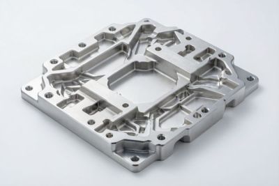
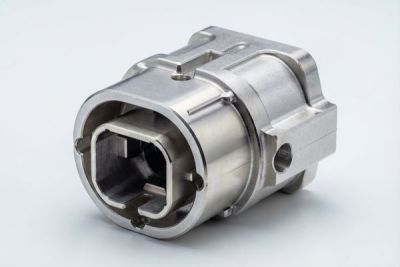
Invar Machining for Optical Components: Mirror Bases 2026 Guide
If you are specifying a mirror base for a laser, lithography, or metrology stage, you already know the real enemy is heat. A shift of just a few tenths of a degree across the base moves your optic by more than your error budget allows, and no amount of software correction brings it back. The reference plane has to stay still on its own.
This guide walks through why invar machining wins for thermal stability, how a precision base is actually held to +/-0.005 mm and a Ra 0.2 um mirror finish, the alloy trade-offs you should weigh before releasing a drawing, and the five documents you must demand from any shop before you commit a program.
We write this from the bench, not the brochure. At Dongguan Licun Technology (LusterControl) we have run invar 36 and invar 42 mirror bases and lens barrels for optics and semiconductor customers, and the difference between a base that holds calibration and one that drifts almost always comes down to process discipline, not the machine brand.
Table of Contents
- 1. Why Invar Machining Defines Thermal Stability in Optical Components
- 2. What Is Sub-Micron Stability and Why Your Precision Base Needs It
- 3. Invar vs Aluminum vs Stainless: Which Precision Base Wins for Thermal Drift
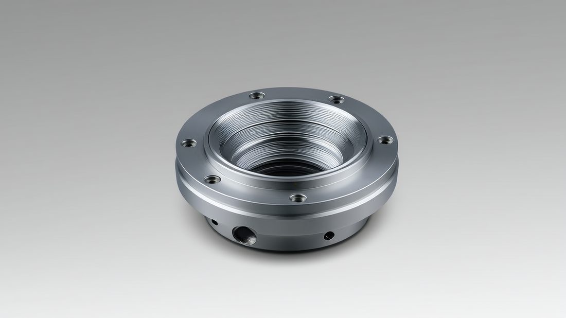
- 4. How Invar Machining Reaches +/-0.005 mm Flatness on Precision Base Plates
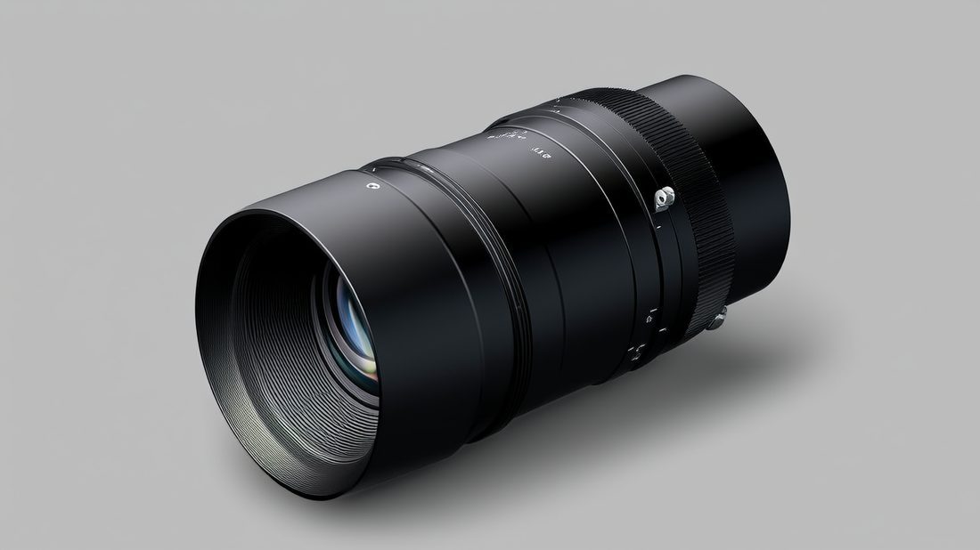
- 5. Lens Barrel Machining for Optical Components: Concentricity Is Everything
- 6. CNC Instrumentation and Surface Finish: From Ra 0.6 to Ra 0.2 um Mirror
- 7. A Buyer's Checklist for Sub-Micron Stability Precision Bases
- 8. Choosing a Machining Partner for Invar Optical Components: What to Verify
Optical AI part image
Why Invar Machining Defines Thermal Stability in Optical Components
Thermal expansion, not cutting force, is what ruins a calibrated optical assembly.
The coefficient of thermal expansion (CTE) is the number that decides your material. Invar (a 36% nickel iron alloy) sits near 1.2 x 10^-6/K, while aluminum 7075 is about 23.6 and stainless 304 about 17.3. Run the math on a 300 mm base across a 1 degree C swing and aluminum grows roughly 6.9 um while invar moves only 0.36 um. If your spec is sub-micron, aluminum is already out of the race before the first cut.
What CTE is, and why it decides your material
- Coefficient of thermal expansion (CTE)
- The fractional change in length per degree Kelvin. Lower CTE means less drift under temperature change.
- Invar 36
- A 36% nickel iron alloy with CTE near 1.2 x 10^-6/K - the workhorse for thermally stable optical bases.
- Super Invar / heat-treated Invar 36
- CTE can drop to about 0.6 x 10^-6/K after strict thermal cycling, used in the most demanding metrology bases.
You do not choose invar because it is easy to machine - it is not. You choose it because nothing else in the affordable structural-metals league holds your reference plane still. The real question becomes whether your shop can actually machine it to the flatness and finish your optic demands. That is where invar machining skill separates a usable base from a drift-prone one.
For the broader picture on thermally stable structures, see our optical components machining guides covering bases, barrels, and mounts.
Optical AI part image
What Is Sub-Micron Stability and Why Your Precision Base Needs It
Sub-micron stability is a system property, not a single tolerance on a drawing.
Sub-micron stability means the position of your optic or reference surface stays within +/-1 um (ideally +/-0.2 to 0.5 um) across the full operating temperature, load, and time envelope. It is the sum of four things: material drift, mounting strain, surface flatness, and fastening creep. Write a flatness call-out and you have addressed maybe a quarter of the problem.
- Sub-micron stability
- Holding a reference surface within +/-1 um (often +/-0.2 to 0.5 um) of nominal under real operating conditions.
- Flatness
- Deviation of a surface from a perfect plane, measured in um over a given span.
- Mounting strain
- Residual stress introduced by clamps or bolts that bends the base the instant you tighten it.
Three drift sources you must budget for
- Material CTE drift - the base itself grows and shrinks with temperature.
- Mounting strain - over-tightening bolts bows the plate; use kinematic or low-clamp mounts.
- Surface relaxation - a poorly stress-relieved blank keeps moving for weeks after machining.
A precision base that reads flat in the metrology room can drift microns once it is bolted into a frame that runs 8 degrees C warmer. We stress-relieve every invar blank with a controlled thermal cycle before roughing, so the part you receive is already past its relaxation phase and will not surprise you on the bench.
Invar vs Aluminum vs Stainless: Which Precision Base Wins for Thermal Drift
Pick the alloy by the drift budget, not by the catalogue price.
| Property | Invar 36 | Aluminum 7075 | Stainless 304 |
|---|---|---|---|
| CTE (x10^-6/K) | 1.2 | 23.6 | 17.3 |
| Density (g/cm3) | 8.1 | 2.81 | 7.9 |
| Machinability (relative) | Low | High | Medium |
| Flatness typically held | +/-0.005 mm | +/-0.01 mm | +/-0.008 mm |
| Best use | Stable references | Lightweight, non-critical | Corrosive or wet labs |
Choose invar if
- Your drift budget is under 1 um over the operating window
- The base is a primary reference plane (interferometer, lithography stage)
- You can tolerate higher mass and a longer cycle time
Choose aluminum if
- Mass matters more than drift (UAV gimbals, handheld optics)
- Tolerances are in the 10 to 20 um range
- You need fast, cheap volume production
Be honest with yourself: aluminum wins on weight and cost, but it will not hold sub-micron stability unless you actively temperature-control the entire instrument. If you cannot control temperature, you cannot use aluminum for the reference - full stop.
Pros
- Near-zero thermal drift
- Stable, repeatable reference plane
- Proven in metrology for decades
Cons
- Heavy at 8.1 g/cm3
- Work-hardens, slow to cut
- Costs more than steel or aluminum
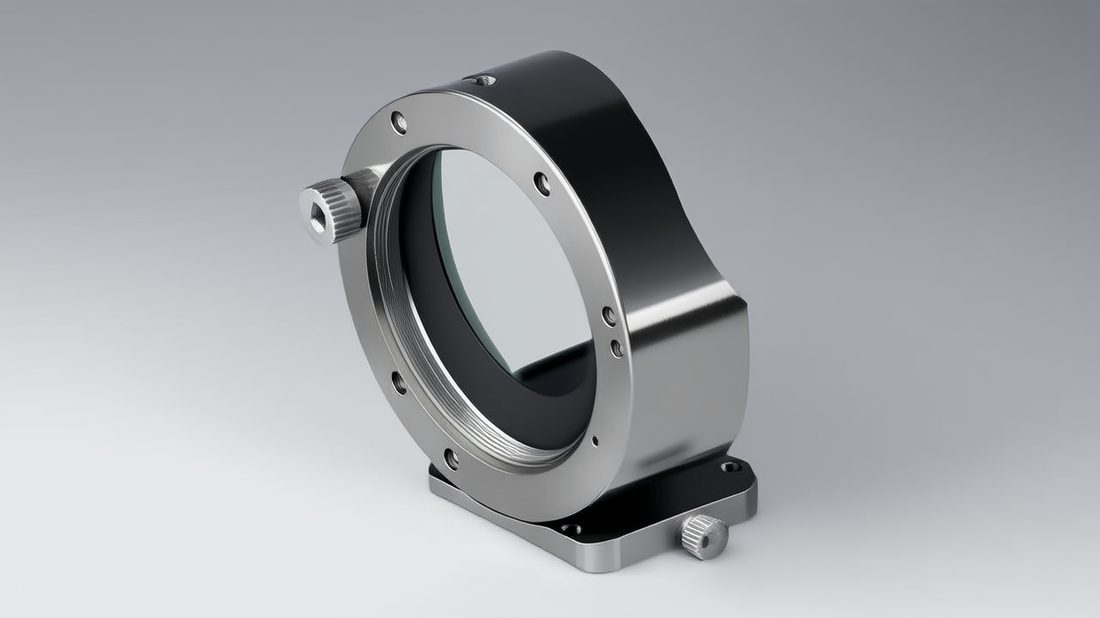
Optical AI part image
How Invar Machining Reaches +/-0.005 mm Flatness on Precision Base Plates
Flatness is earned in the process chain, not at the final pass.
Step 1 - Stress-relieve the blank
Invar work-hardens and carries internal stress from rolling and rough cutting. We thermal-cycle each blank (heat to about 300 degrees C, slow cool) before any cutting. Skip this and the plate keeps moving after delivery - usually right after your customer integrates it.
Step 2 - Rough, rest, finish
- Rough 0.3 mm oversize on all datums
- Age and rest 24 to 48 hours so stress redistributes
- Semi-finish to 0.05 mm
- Final skim at low depth of cut with sharp inserts
- Lap or diamond-fly-cut the reference face to +/-0.005 mm
Step 3 - Measure on a temperature-controlled granite
We verify flatness on a granite table at 20 +/-0.5 degrees C and report a traceable first-article inspection. For mirror bases we often diamond-fly-cut the optical seat to Ra 0.2 um (8K) so the bonded optic seats without adhesive voids that would otherwise scatter your beam.
Talk to our engineering team in Dongguan about your invar machining program and we will flag the riskiest tolerance before you cut steel.
Lens Barrel Machining for Optical Components: Concentricity Is Everything
A lens barrel's only job is to keep every element on one axis - to +/-0.005 mm.
The barrel is the spine of an optical component assembly. If the bores are not concentric, your elements tilt and you get coma and focus shift even with perfect lenses. We cut barrels from solid invar or 6061/7075 on turn-mill or 5-axis centers so the bore, register, and thread are cut in one setup - no re-chuck, no stack-up error.
Concentricity targets by application
| Application | Bore concentricity | Typical finish |
|---|---|---|
| Consumer or industrial lens | +/-0.02 mm | Ra 0.8 um |
| Lab or medical optic | +/-0.005 mm | Ra 0.4 um |
| Metrology or interferometer | +/-0.002 mm | Ra 0.2 um (8K) |
Single-setup machining is the trick. Holding the barrel in a collet and cutting internal and external features without re-chucking removes the re-clamp error that quietly kills concentricity. Our Swiss-type and turn-mill centers do exactly this, which is why our lens barrel machining holds interferometer-class numbers on the first run.
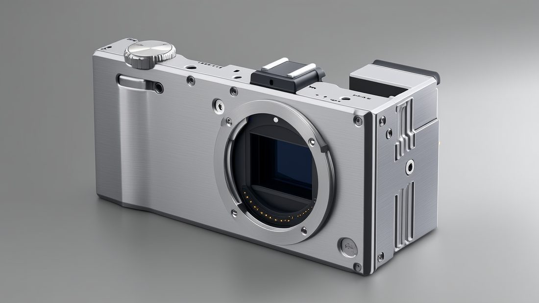
Optical AI part image
CNC Instrumentation and Surface Finish: From Ra 0.6 to Ra 0.2 um Mirror
Finish is not cosmetic on a mirror base - it changes how your optic bonds and scatters.
Rough seats trap adhesive and create voids; a mirror finish (Ra 0.2 um, 8K) gives a void-free bond line and lower scatter. We reach it with fine diamond tooling, electrolytic polish, or diamond fly-cutting depending on the alloy and geometry.
Finish tier decision table
| Finish | Ra | Method | Use |
|---|---|---|---|
| Standard | <=0.6 um | CNC finish pass | Non-optical mounts |
| Fine | <=0.4 um | Fine turn plus lap | Lab optics |
| Mirror (8K) | <=0.2 um | Diamond fly-cut or electropolish | Bonded mirrors, beam seats |
Our CNC instrumentation includes in-process probing and a controlled clean bench so the finished base is not re-contaminated before it ships. On stainless seats we apply ASTM A967 passivation to remove free iron and prevent creep corrosion under the optic - a small step that protects a very expensive assembly.
A Buyer's Checklist for Sub-Micron Stability Precision Bases
Five documents you should demand before you release a drawing.
- Material cert (mill heat number plus CTE confirmation for invar 36 or 42)
- Stress-relief or thermal-cycle record for the blank
- First-article inspection (flatness, concentricity, CTE if claimed)
- Lot traceability - heat number tied to your PO and serial number
- Surface finish report (Ra value on the optical seat, not just 'polished')
If a shop cannot show you the stress-relief record, assume the base will move after delivery. That single document predicts more field failures than any tolerance on the drawing, yet it is the one most often left out of a quote.
Common mistakes that make a base drift
- Specifying invar but accepting an aluminum 'equivalent' substitute
- Tolerancing the seat tighter than the measuring method can prove
- Forgetting to state the operating temperature range on the drawing
- Using over-tightened bolts that bow the plate (use kinematic mounts)
- Skipping CTE confirmation on the supplied heat
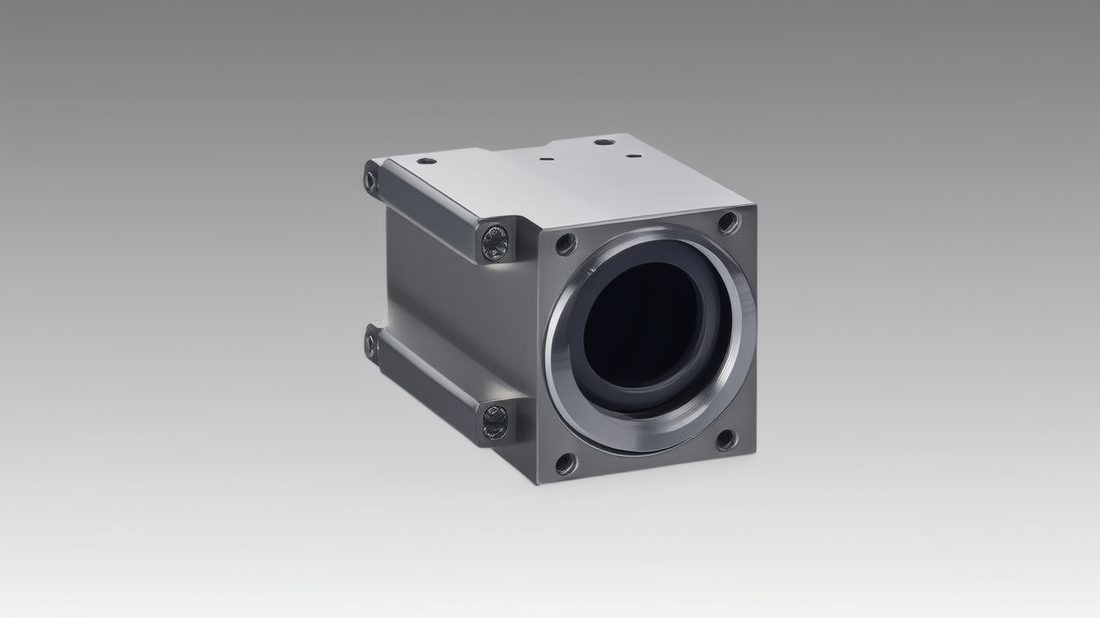
Optical AI part image
Choosing a Machining Partner for Invar Optical Components: What to Verify
Capability on paper is cheap; proof on the pallet is what matters.
Before you commit a precision base program, verify the shop can actually hold what it quotes. Ask for a first-article on a representative feature, not a sales deck. We have supplied precision parts to appliance OEMs such as De'Longhi, Donlim, and Breville, and a UAV customer's first order exceeded 1.2 million RMB - the discipline that earns that trust is the same discipline your optical base needs.
Verification matrix
| Claim to verify | How to verify | What good looks like |
|---|---|---|
| +/-0.005 mm flatness | Ask for FAI on granite at 20 degrees C | Traceable report, not a verbal 'yes' |
| Invar CTE | Mill cert plus heat number | CTE about 1.2 x 10^-6/K confirmed |
| Mirror finish | Ra measurement on the seat | <=0.2 um on the optical face |
| Volume repeatability | PPAP or lot Cp/Cpk if needed | Stable across the whole PO |
Browse our technical guides on optical components or send your drawing for a free DFM review before you release the program.
Optical AI part image
Optical AI part image
Optical AI part image
Optical AI part image
FAQ: optical components & Optical Buyer Questions
A: Invar 36 (CTE about 1.2 x 10^-6/K) for most sub-micron bases; Super Invar or heat-treated invar 36 for the tightest drift budgets; glass-ceramic (Zerodur) if you need even lower CTE and can accept brittle, costly material. Aluminum only works if you actively control the instrument temperature.
A: We hold +/-0.005 mm flatness on precision base plates and diamond-fly-cut optical seats to Ra 0.2 um (8K mirror finish). First-article is measured on a temperature-controlled granite at 20 +/-0.5 degrees C and reported with traceable data.
A: Invar work-hardens and carries internal stress from rolling and rough cutting. Without a controlled thermal cycle the blank keeps relaxing for weeks and your 'flat' base drifts microns after delivery. We thermal-cycle every blank before roughing.
A: Yes. For metrology-grade optical components we cut barrels in a single setup on turn-mill or 5-axis centers so bore, register, and thread share one datum, holding +/-0.002 mm concentricity on interferometer-class barrels.
A: Every lot ships with mill material certs (heat number plus CTE), a stress-relief record, and first-article inspection covering flatness, concentricity, and surface finish. We are ISO 9001 certified, ISO 13485 completed, and IATF 16949 in application.
A: State the operating temperature range, demand a stress-relief record, require single-setup or matched-fixture machining for tight bores, use kinematic or low-clamp mounts, and ask for Ra on the optical seat (not just 'polished'). Send the drawing early for a free DFM review.
Send us your drawing for a free DFM review - we will flag the tolerance or finish call that could otherwise cost you a two-week rework loop on your invar optical base.
Request a Free CNC Quote