Precision Mold Inserts and Guide Pins: A 2026 Tooling Guide
If your injection or die-cast parts are drifting out of tolerance, showing flash, or throwing scrap after only a few thousand shots, the root cause is usually not the molding machine—it is the tooling. The mold inserts, guide pins, and wear blocks that actually define the cavity and keep the halves aligned decide your yield long before resin ever touches steel.
This 2026 guide walks you through the tooling components that quietly control your cost per part: what each one does, how it is machined, which steel and tolerance to specify, and—most importantly—what to verify before you place an order. We write it from the buyer's and toolroom's seat, not the sales desk, so you can read a spec sheet and know exactly what protects your cycle time.
Every number you will see tied to a supplier is drawn from a real source factory: Dongguan Licun Technology Co., Ltd. (brand LusterControl), a Dongguan, China precision CNC shop running 60+ machines, holding ±0.005 mm, and finishing stainless to an 8K mirror of Ra 0.2 µm under ISO 9001 and ISO 13485.
Table of Contents
- 1. What Are Mold Inserts, and Why Do They Decide Your Molding Yield?
- 2. How Guide Pins Keep Your Molds Aligned: Tooling Machining Basics
- 3. Wear Blocks and Guide Rails: Where Friction Quietly Kills Cycle Time
- 4. H13 Steel Machining: Heat Treatment, Hardness, and Dimensional Stability
- 5. Precision Jigs vs. Fixtures: When Each One Saves You Setup Hours
- 6. Tooling Machining Tolerances: Why ±0.005 mm Matters for Insert Fit
- 7. How to Choose Mold Inserts and Guide Pins for Your Application
- 8. Common Tooling Machining Mistakes That Crack Inserts Prematurely
- 9. Sourcing Precision Jigs and Mold Inserts: A Buyer's Checklist
Tooling&Fixtures AI part image
What Are Mold Inserts, and Why Do They Decide Your Molding Yield?
Before you spec a single dimension, understand the part that actually touches your resin.
- Mold insert
- A replaceable, precision-machined block that forms one feature of the cavity or core—typically the wear-prone or frequently changed geometry, so you re-cut an insert instead of the whole mold base.
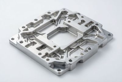
A mold base can be built once and run for years; the inserts are the consumable. When an edge chips, a gate wears, or you need a second variant of the same part, you swap the insert—not the frame. That single design decision is what lets a toolroom keep a press running instead of stripping the mold. For the buyer, it means your per-part cost stays flat even as geometry evolves, and your lead time for a variant drops from 'rebuild the mold' to 'machining a fresh insert'.
Core inserts vs. cavity inserts: what changes first
Core inserts form the internal shape (the 'male' feature); cavity inserts form the external envelope. In abrasive or glass-filled resins, the cavity and the gate typically wear fastest because they take the highest shear at the parting line. When we plan a tool for a De'Longhi or Donlim coffee-machine component, we deliberately make those faces insert-based and mirror-finished so a worn face is a one-hour swap, not a week of downtime. The release face is where surface finish matters most: a polished 8K face (Ra 0.2 µm) lets parts eject without sticking, which is why we invest in mirror and electropolishing rather than leaving a mill finish.
Why buyers should request inserts as separate components
Ask your shop to deliver inserts as individually dimensioned, individually inspected components—not 'part of the mold.' When you hold that line, you get first-article data per insert, you can re-order one cavity without a full mold quote, and you can move an insert to a different base if your volume shifts. If you are scoping a new tool and want an honest read on which faces should be insert-based, send us your drawing for a free DFM review and we will flag the high-wear zones before steel is cut.
Tooling&Fixtures AI part image
How Guide Pins Keep Your Molds Aligned: Tooling Machining Basics
Misalignment shows up as flash, binding, and scrap—guide pins are your first line of defense.
- Guide pins (leader pins)
- Hardened, ground steel pins in the fixed half that enter bushings in the moving half, dictating repeatable parting-line alignment shot after shot.
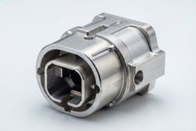
Every time the mold opens and closes, the moving half must land in the same place within a fraction of a millimeter. Guide pins and their bushings are the mechanical reference that enforces that repeatability. If the pin diameter is undersized, the bearing surface is rough, or the fit is sloppy, the halves drift, the parting line opens, and you start seeing flash on every part. In high-cavity tools the cost compounds: one misaligned cavity throws the whole shot to scrap.
The three-stage tooling machining flow for guide pins
- Material selection and pre-hardening—start from a grade that survives shear and sliding wear, then harden before final grinding so the bearing diameter is stable.
- Turn-mill compound + cylindrical grinding to hit ±0.005 mm on the diameter and a low Ra on the bearing surface, so the pin slides instead of galling.
- Fit verification against the bushing with a go/no-go check, and a logged batch record so every pin is traceable to its heat-treat lot.
What alignment drift costs you in scrap
A guide pin that is 0.01 mm loose at the bushing does not look broken—but over 50,000 cycles it lets the moving half walk, and your flash band widens until the deburring step alone eats your margin. The fix is cheap upstream: spec the pin diameter, the bushing bore, and the concentricity together, and have the shop prove all three. We machine leader pins and bushings on the same turn-mill cells that run our automotive and robotics components, which is why the same ±0.005 mm discipline applies to both.
Wear Blocks and Guide Rails: Where Friction Quietly Kills Cycle Time
Slide wear is invisible until your ejection force spikes and your cycle time creeps up.
- Wear blocks
- Interchangeable hardened plates that absorb the sliding load between mold halves or slides, protecting the base steel and letting you swap the worn face instead of the whole assembly.
Slides, lifters, and unscrewing mechanisms all move against a fixed face under clamp tonnage. Without a sacrificial wear block, that load grinds directly into the mold base, and after a few hundred thousand cycles the slide starts to bind. Binding means higher ejection force, slower cycles, and eventually a seized slide. Wear blocks turn that slow death into a planned, ten-minute swap.
Where wear blocks earn their keep
- Any slide or angle-lifter that moves every cycle under clamp load.
- Hot-runner manifolds where thermal growth keeps stressing the locating faces.
- High-volume tools where a single seized slide stops the whole press.
- Tools running filled or glass-reinforced resins that accelerate abrasion.
| Surface on the sliding face | Typical Ra | Relative service life | When to choose it |
|---|---|---|---|
| As-machined | Ra 1.6 µm | Baseline | Low-volume or prototype tooling |
| Nitrided / hard-coated | Ra 0.8 µm | 2–3x baseline | Filled resins, long runs |
| Mirror-polished (8K) | Ra 0.2 µm | Best release + wear | Sticking-prone or food/medical parts |
Tooling&Fixtures AI part image
H13 Steel Machining: Heat Treatment, Hardness, and Dimensional Stability
H13 is the workhorse of hot-runner and high-cycle tooling—but only if the machining and heat-treat sequence is right.
- H13 (1.2344)
- A chromium-molybdenum hot-work tool steel, typically hardened to 44–52 HRC, favored for molds and dies that see heat, pressure, and abrasion.
H13 earns its place in high-cycle and hot-runner tooling because it resists heat-checking and holds an edge under pressure. But H13 is unforgiving about process order: machine it hard and it work-hardens under the tool; heat-treat it after finish-machining and it distorts. The disciplined sequence is to rough machine soft, leave stock, heat treat, then finish-grind and CNC the features that must be accurate. Skipping that order is the fastest way to a warped insert that no amount of polishing will save.
Machining H13 before vs. after heat treatment
We rough all H13 inserts in the annealed state, then send them for vacuum hardening and double tempering. Only after the steel is stable do we finish the bores, pockets, and parting faces to ±0.005 mm. This is the step that protects dimensional stability: a finished insert that was cut before hardening can move by more than your tolerance band during the quench. Holding the final features after heat treat is non-negotiable for inserts that must drop into a pocket by hand.
| Grade | Typical hardness | Corrosion resistance | Best use for mold inserts |
|---|---|---|---|
| H13 (1.2344) | 44–52 HRC | Moderate | Hot-runner, high-cycle, abrasive resins |
| S136 (stainless) | 48–52 HRC | High | Medical, food-contact, corrosive resins |
| P20 | 28–35 HRC | Low–moderate | Prototype or low-volume, pre-hardened |
Dimensional stability: why we hold ±0.005 mm on finished inserts
For interchangeable inserts the tolerance is not a bragging number—it is what lets the part seat repeatably under clamp load without rocking. Hold it loose and the insert migrates; hold it to ±0.005 mm and it drops in, stays put, and your cavity position holds shot after shot. That is the tolerance band we commit to on finished H13 and stainless inserts.
Precision Jigs vs. Fixtures: When Each One Saves You Setup Hours
Tooling is not only what goes inside the mold—it is how you hold the workpiece while you make it.
- Precision jigs
- Devices that both locate and guide the cutting tool (for example a drill jig); fixtures locate and clamp the part so a CNC or manual operation repeats without re-indicating.
When you are making the tooling itself—drilling cooling channels, boring guide-pin bushings, spot-facing pocket seats—the repeatability of those holes decides whether the finished mold aligns. A jig guides the drill straight into the right spot every time; a fixture holds the block so the CNC repeats the same program without re-clamping and re-indicating. Both remove human judgment from the loop, which is exactly where setup hours and scrap come from.
Choose a jig when… and a fixture when…
- Use a jig when the same hole pattern repeats across many identical blocks and you want the tool guided, not just the part located.
- Use a fixture when the part is large, awkward, or thin-walled and the risk is movement under clamping, not drill wander.
- Use both together for high-mix tooling where one fixture base takes several jig plates for different hole maps.
| Need | Reach for | What it saves you |
|---|---|---|
| Repeat identical holes fast | Drill / bore jig | No re-layout per block |
| Hold an awkward part still | Fixtures | No re-clamp or re-indicate |
| Mixed hole maps on one base | Modular fixture + jig plates | One setup, many variants |
Tooling&Fixtures AI part image
Tooling Machining Tolerances: Why ±0.005 mm Matters for Insert Fit
A thou here, a thou there—and your insert rocks in the pocket.
- Fit tolerance
- The permitted variance between mating surfaces; for interchangeable inserts it decides whether a part drops in by hand or needs a mallet—and whether it stays put under clamping.
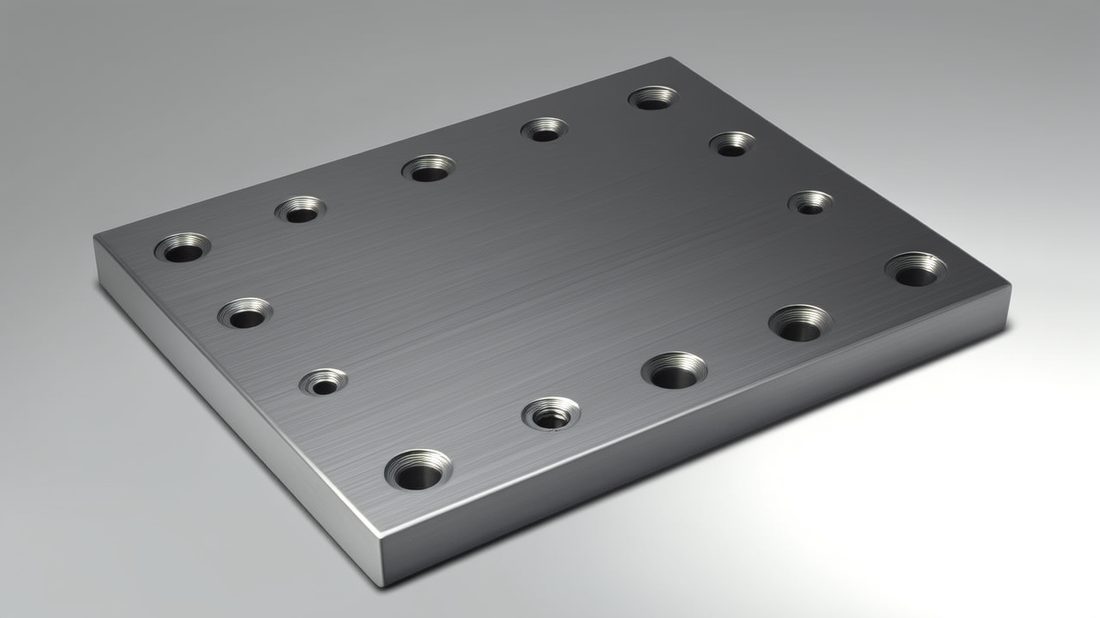
Tolerances on tooling are not uniform—they are concentrated where motion and fit happen. The guide-pin bore, the insert pocket, and the parting-line seat are the three zones where a loose number turns into flash, binding, or a rocking cavity. The rest of the block can be comparatively open; over-tolerancing everything just adds cost and cycle time with no yield benefit. A good toolroom tells you exactly which features are tight and why.
Where tight tolerance is non-negotiable
- Guide-pin bores and bushings—alignment lives or dies here.
- Insert pockets—a rocking insert throws every cavity out of position.
- Parting-line seats—loose here equals flash on every shot.
- Cooling-channel registration—misaligned channels cause hot spots and warpage.
| Feature | Why it is tight | What we hold |
|---|---|---|
| Guide-pin bore | Repeatable alignment | ±0.005 mm |
| Insert pocket | No rocking under clamp | ±0.005 mm |
| Parting-line seat | No flash band | ±0.005 mm |
| Non-critical wall | Cost control | ±0.02 mm typical |
How to Choose Mold Inserts and Guide Pins for Your Application
A short decision path that turns your resin, volume, and cycle target into a spec sheet.
Step 1 — characterize your resin and duty
Start from what runs through the tool. Glass-filled or mineral-filled resins are abrasive and demand hardened, wear-resistant faces; corrosive or food-contact resins demand stainless; high-cycle hot-runner tools demand a grade that resists heat-checking. Write down resin, expected shot count, and whether the part is cosmetic or structural—that list is 80% of the material decision.
Step 2 — match material to duty, then tolerance to fit
With the duty known, the steel almost selects itself: H13 for heat and abrasion, S136 stainless for corrosion and medical, P20 for low-volume pre-hardened work. Then decide the fit zones that must be tight (guide bores, pockets, parting seats) and open up the rest. If you want to cross-check your plan against real production examples across automotive CNC parts and mold tooling articles, our technical library walks through several duty-to-steel mappings.
| Your duty | Recommended insert / pin | Why it wins |
|---|---|---|
| Abrasive filled resin, high cycle | H13, nitrided + mirror face | Wear resistance + clean release |
| Medical / food-contact part | S136 stainless, ASTM A967 passivated | Corrosion resistance + cleanability |
| Low-volume prototype | P20 pre-hardened | Fast, low-cost, no heat treat |
| Tight-tolerance alignment | Guide pins + bushings at ±0.005 mm | Repeatable parting line, no flash |
Tooling&Fixtures AI part image
Common Tooling Machining Mistakes That Crack Inserts Prematurely
Most insert failures are designed in before the first shot—here is what to avoid.
- Undersizing the guide-pin diameter for the mold weight, so the moving half walks and the parting line opens into flash.
- Skipping passivation on stainless inserts (per ASTM A967), letting microscopic pits nucleate corrosion that propagates under clamp stress.
- Polishing the release face but leaving a steep step at the edge that traps resin and tears the part on ejection.
- Ignoring incoming batch traceability on heat-treated steel, so a bad melt is impossible to isolate when inserts crack.
- Tolerancing the pocket tighter than the process can hold repeatably, then fighting fit with a mallet—which pre-stresses the insert.
These are not theoretical. On coffee-machine components we supply to De'Longhi, Donlim, and Breville, the difference between a 200,000-shot life and a 20,000-shot failure usually traces back to one of the five items above—almost never to the molding parameters. Getting the tooling right upstream is cheaper than debugging scrap on a running press.
Sourcing Precision Jigs and Mold Inserts: A Buyer's Checklist
Before you send a PO, ask for these five things—every serious tooling shop should hand them over without hesitation.
- Material certificate (mill cert) for H13 / S136 / P20—proof of grade, not a promise.
- Heat-treatment record with a hardness map across the insert, not a single surface reading.
- First-article inspection (FAI) report measured against your drawing, with the tight fit zones called out.
- Incoming batch traceability—we keep lot records so any future crack is isolatable to a melt.
- Surface-finish evidence: Ra measurement on the release and sliding faces, not just 'polished'.
- A lead-time curve for repeat orders, so your reorder does not become a fire drill.
If a shop hesitates on any of the six items above, that hesitation is your red flag. Tooling is a long-lived asset; the documentation you collect at order time is what protects you when a cavity finally wears out two years from now.
Tooling&Fixtures AI part image
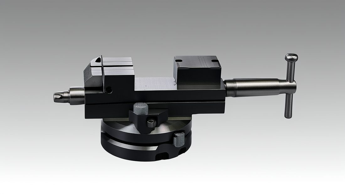
Tooling&Fixtures AI part image
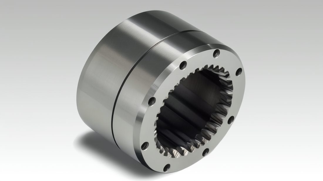
Tooling&Fixtures AI part image
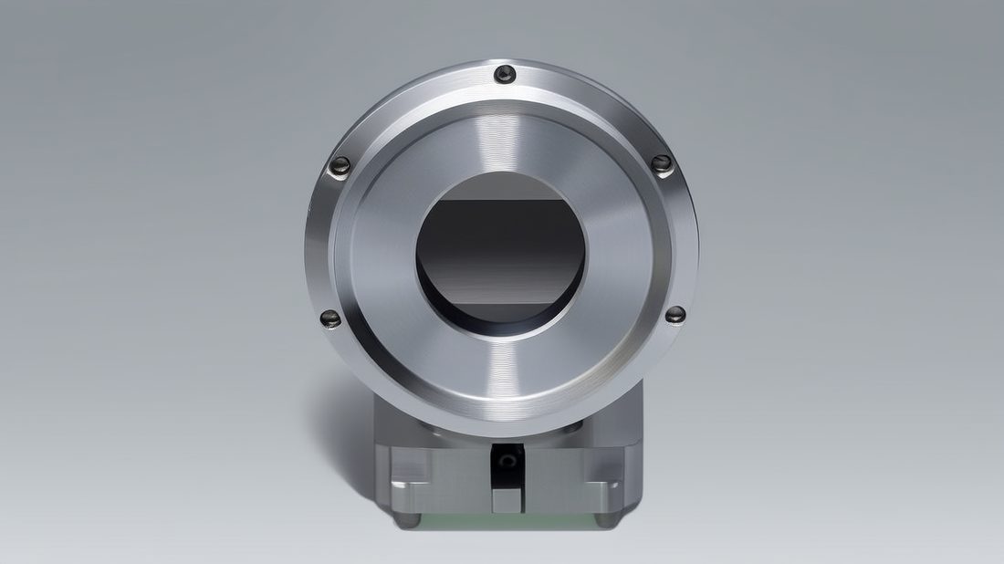
Tooling&Fixtures AI part image
FAQ: mold inserts & Tooling&Fixtures Buyer Questions
A: For the fit zones that matter—guide-pin bores, insert pockets, and parting-line seats—a disciplined CNC shop holds ±0.005 mm. Non-critical walls can stay open at roughly ±0.02 mm to control cost. LusterControl commits to ±0.005 mm on finished H13 and stainless inserts after heat treatment.
A: For glass- or mineral-filled resins at high cycle counts, H13 (1.2344) hardened to 44–52 HRC with a nitrided or mirror-polished face is the standard choice for wear resistance and clean release. Move to S136 stainless only when corrosion or food/medical contact is the constraint.
A: Guide pins and bushings are the mechanical reference that lands the moving half in the same place every cycle. If the pin diameter or bushing bore is loose by even 0.01 mm, the parting line can drift and open a flash band on every shot. Tightening the pin-and-bushing fit is often the first fix for flash.
A: Yes. Interchangeable inserts are the recommended design for multi-cavity and variant tools: each cavity is a separately dimensioned, separately inspected component that drops into a pocket by hand. You can reorder one cavity without requoting the whole mold, and move an insert between compatible bases as volume shifts.
A: Your 3D drawing with the tight fit zones called out, the resin and expected shot count, the required steel grade, any surface-finish spec (for example Ra 0.2 µm on release faces), and your target volume. With those, a shop can return a DFM review, a tolerance plan, and a realistic lead time.
A: Electropolishing removes micro-burrs and passivates the surface, lowering Ra and eliminating pits where bacteria or residue collect. For S136 stainless inserts in medical or food-contact tools, it pairs with ASTM A967 passivation to improve cleanability and extend service life.
Send us your drawing and resin data sheet—our engineers will return a DFM review and a tolerance plan for your mold inserts, guide pins, and wear blocks at no cost.
Request a Free CNC Quote