Robotics Makers Shift to Turn-Mill Housings for Harmonic Drives (2026)
If you design collaborative robots or articulated arms, you already know the joint is the product. A harmonic drive packs a 30:1 or even 100:1 reduction into a cylinder the size of a coffee mug, which is exactly why it shows up in nearly every modern robot joint. But the gear is only as good as the housing that holds it - and that housing is where most sourcing teams quietly lose their zero-backlash promise.
In this guide we walk through why robotics makers are moving away from glued-together lathe-and-mill stacks toward single-setup turn-mill compound machining for their robot joint parts. We cover how a harmonic drive actually loads its strain-wave bearing, where the tolerance budget really has to live, why aluminum 7075 machining wins the weight war for cobot joints, and what to demand from a supplier before you approve a first article. Everything here is written from the shop floor at Dongguan Licun Technology, not a catalog.
We have machined precision CNC parts since 2015 - fifteen years of stainless mirror finishing and tight-tolerance work - and we run 60 CNC machines across a 4,000 square meter Dongguan facility with monthly output around 500,000 pieces. The numbers and trade-offs below are the ones we argue about with robot engineers before a single chip is cut.
Table of Contents
- 1. Why Robotics Makers Rethink Robot Joint Parts for Harmonic Drives
- 2. How Harmonic Drive Parts Deliver 30:1 Reduction in a Tiny Package
- 3. Why Turn-Mill Compound Machining Wins for Housing Geometry
- 4. Aluminum 7075 Machining for Lightweight Harmonic Drive Housings
- 5. What Tight Tolerance CNC Means for Strain-Wave Bearings
- 6. CNC Precision Machining of Robot Joint Parts: A Process Walkthrough
- 7. Machined Housing vs Die-Cast: Choosing Harmonic Drive Parts
- 8. A Buyer's Checklist for Sourcing Robot Joint Parts
- 9. Common Sourcing Mistakes for Harmonic Drive Parts
Robotics AI part image
Why Robotics Makers Rethink Robot Joint Parts for Harmonic Drives
The joint is the product; the housing is the part that decides if the gear stays honest.
A harmonic drive delivers huge reduction in a small, light package, but it is unforgiving about alignment. The flex spline is a thin-walled cup that flexes elliptically thousands of times per minute, and the wave generator bearing that forces that ellipse must sit perfectly concentric with the rigid circular spline. If the housing bores drift by even 0.02 mm, the wave generator binds, the bearing preload spikes, and the joint either runs hot or loses its rated torque. Your robot joint parts are, in practice, an alignment problem disguised as a gear problem.
That is why the conversation about harmonic drive parts has shifted upstream to the housing geometry. Buyers who used to spec the gear and hand the envelope to a cheap bracket shop now realize the bracket is load-bearing for the entire reduction. Get the concentricity and flatness right and a standard gear performs to its datasheet; get them wrong and even a premium gear chatters.
What actually fails in the field
- Wave generator bearing skidding from bore eccentricity
- Circular spline rocking because the mounting face is not flat to datum
- Lost motion creeping in after a few thousand cycles from a loose pilot
- Heat soak warping a thin-wall housing that was fine on the CMM at 22 C
If you want to see how this single-setup philosophy carries into other precision programs, our robot joint parts and harmonic drive guides cover related work in the same alignment-first mindset.
Robotics AI part image
How Harmonic Drive Parts Deliver 30:1 Reduction in a Tiny Package
Three parts, one ellipse, and a tolerance you can feel in the wrist.
- Harmonic drive
- A strain-wave gear set using a flexible spline, a rigid circular spline, and an elliptical wave generator to achieve high reduction in a compact, zero-backlash package.
- Wave generator
- The elliptical cam plus a thin-section bearing that deforms the flex spline into an ellipse inside the circular spline.
- Flex spline
- A thin-walled cup with external teeth that engage the circular spline at the ellipse major axis only, producing the reduction.
A harmonic drive has three core components. The wave generator is an elliptical plug riding on a thin-section bearing. The flex spline is a flexible cup with external teeth. The circular spline is a rigid ring with internal teeth. As the wave generator turns, the flex spline teeth mesh with the circular spline only at the two ends of the ellipse, so each input revolution advances the flex spline by a tiny arc - hence the high ratio.
Why the housing is the silent third component
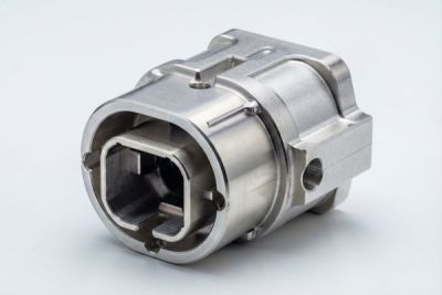
The circular spline and the wave generator bearing both seat into the housing. Their relative concentricity is set entirely by the housing bores and faces, not by the gear. This is the part most teams underestimate: you can buy a 1-arc-min harmonic drive and wreck it with a 0.03 mm housing error. So when we talk about harmonic drive parts, the housing is half the spec.
| Feature | What the gear needs | What the housing must provide |
|---|---|---|
| Circular spline seat | Internal tooth ring, fixed | Bore held to H7, flat face to datum within 0.02 mm |
| Wave generator bearing | Runs at ellipse major axis | Coaxial bore within 0.01 mm of circular spline seat |
| Pilot / register | Locates flex spline | Pilot diameter h7, true position +/-0.03 mm |
| Sensor pocket | Encoder or resolver | Mill pocket, datum-referenced, not a second setup |
Why Turn-Mill Compound Machining Wins for Housing Geometry
A harmonic housing is half a lathe part and half a mill part - cut it in one place or pay in datum shift.
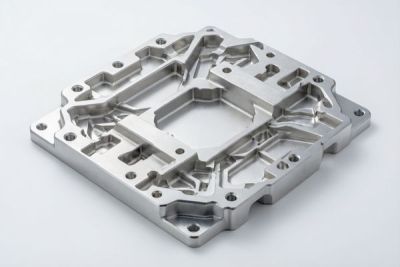
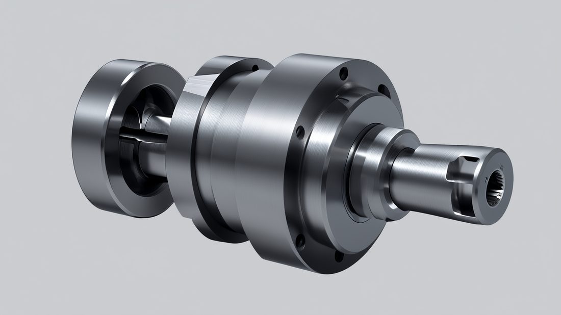
Look at a typical robot joint housing and you see the conflict: the circular spline bore, the outer diameter, and the pilot are turned features that want a lathe; the bolt circle, the locating flat, the encoder pocket, and the cable routing are milled features. Run it as two operations - turn on a lathe, then move to a machining center - and you introduce a re-clamp every time you release the datum. Each re-clamp is a chance to lose 0.02 to 0.05 mm of true position.
Turn-mill compound machining cuts both in a single chucking. The part stays on one datum while the turret turns it and live tooling mills the features. We hold positional accuracy to +/-0.005 mm across turned and milled features because the coordinate system never moves. For a harmonic housing that means the bolt circle stays true to the bore without a second setup, and the encoder pocket lands where the resolver expects it.
Swiss-type advantage for small bores
For the smaller joint sizes, our Swiss-type lathes (Swiss screw machines with live milling) deliver the same single-setup benefit with superior support right at the cutting zone - critical when the circular spline bore is under 40 mm and the wall is thin. The guide bushing keeps the stock rigid until the last moment, so the thin web between bores does not bell out under the end mill.
Pros
- One setup, no datum shift between turned and milled features
- Concentricity of bores held to +/-0.005 mm
- Shorter lead time, fewer fixtures to qualify
- Swiss support for small, thin-wall bores
Cons
- Higher machine-hour rate than a plain lathe
- More programming upfront
- Not worth it for simple, flat-back brackets
| Approach | Concentricity risk | Best for |
|---|---|---|
| Lathe + separate mill | 0.02-0.05 mm per re-clamp | Simple brackets, high volume |
| Turn-mill, single setup | None after first chuck | Housings with coaxial bores + milled pockets |
| Swiss-type turn-mill | Lowest on small bores | Sub-40 mm thin-wall harmonic cups |
Robotics AI part image
Aluminum 7075 Machining for Lightweight Harmonic Drive Housings
Every gram at the joint is paid for in battery and in inertia - choose the alloy like an aircraft part.
Cobot and lightweight arm designers live on a mass budget, and the joint is where mass hurts most because it sits at the end of a lever the servo fights every millisecond. Aluminum 7075 machining is the default answer: 7075-T6 lands near 2.8 g/cc with a yield around 500 MPa, so you get steel-like strength at a third of the weight. For a harmonic housing that is often the difference between a 7 kg arm and a 9 kg arm.
The catch is corrosion and coating. 7075 is less corrosion-friendly than 6061, so we anodize nearly every harmonic housing - Type II for a durable matte that hides handling marks, Type III hard coat where the face sees abrasion from a rotating encoder or a slip ring. Remember the coating grows the bore by a few microns; we machine undersize and let the anodize bring it to nominal, otherwise your wave generator bearing suddenly binds.
When 7075 is the wrong call
If the joint sees continuous 80 C plus, or the housing doubles as a structural member taking bending load, we sometimes step to stainless or a heat-treated steel. 7075 also work-hardens less than some grades but still demands sharp tooling and good coolant discipline. We steer customers to 7075 when weight and stiffness-to-weight drive the design, and away from it when sustained heat or structural bending dominates.
| Alloy | Density | Why use it for a harmonic housing |
|---|---|---|
| 7075-T6 | 2.8 g/cc, ~500 MPa yield | Lightweight, stiff, best strength-to-weight for cobot joints |
| 6061-T6 | 2.7 g/cc, ~275 MPa yield | Cheaper, easier, fine for low-stress brackets |
| 304 stainless | 8.0 g/cc | Corrosion-heavy or washdown environments, weight be damned |
| 4140 steel | 7.8 g/cc | Structural load-bearing joints, not weight-sensitive |
What Tight Tolerance CNC Means for Strain-Wave Bearings
Tolerance is a budget - spend it on the three relationships the bearing actually feels.
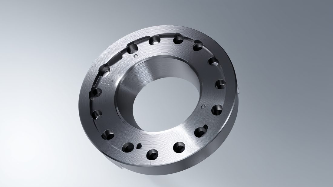
A strain-wave bearing fails quietly when its seats drift. Tight tolerance CNC is not about hitting some heroic number everywhere; it is about spending the budget where the bearing lives. We concentrate it on three relationships: the circular spline bore to the wave generator bore concentricity, the mounting face flatness to that axis, and the pilot true-position that locates the flex spline. Everything cosmetic gets commercial tolerance so the cost stays sane.
Concretely, we hold the two bores coaxial to within 0.01 mm, the mounting face flat to 0.02 mm over the seat, and we inspect the first article on a CMM with a full datum report - not a photo of a caliper. Batch parts get in-process gauging and lot-level CMM audits so a thermal drift in the process shows up before a bad lot ships to your line.
Heat and the free-state problem
Robots run warm. A housing measured perfect at 22 C in our metrology room can bell by 0.01 to 0.02 mm at 60 C if the wall is uneven. We simulate the operating band with customers and, for thin-wall parts, measure the free-state form after relaxing the fixture so the number you get is the number your joint actually sees on the bench - not the clamped fairy tale.
- Confirm material cert traceable to the heat lot
- Agree coated vs bare tolerances before quoting
- Require a CMM first-article report with datums
- Define free-state vs clamped measurement
- Plan fixture relief for thin walls
- Set lot-level traceability from bar to finished part
Robotics AI part image
CNC Precision Machining of Robot Joint Parts: A Process Walkthrough
From raw bar to qualified housing in five disciplined steps.
When an engineering team sends us a joint housing drawing, the clock starts on a predictable path. The goal is never just 'make the shape' - it is 'make the shape that keeps the harmonic drive honest across its rated life.' Here is the walkthrough we run on every robot joint parts program, and our free DFM review is where we flag these issues before cutting metal.
- DFM review: we flag thin walls, sharp internal corners, and bare-bore press-fits that ignore anodize growth, and propose coated-condition tolerances.
- Setup on turn-mill or Swiss-type: rough and semi-finish in one chuck, leaving 0.1 mm for finishing so heat does not lock in distortion.
- Finish bores and faces to +/-0.005 mm, then live-tool the bolt circle, flat, and encoder pocket without releasing the datum.
- Passivate per ASTM A967 (for stainless variants) and anodize (for 7075) so the seats resist handling corrosion.
- CMM first article against the datum scheme; release batch with in-process gauging and full lot traceability.
Why we finish last
Leaving stock for a final pass sounds old-school, but it is the only way to cancel the distortion from roughing heat and clamp stress. On a thin-wall harmonic cup, skipping it means the bore you measure at the machine is not the bore the bearing sees once it relaxes. CNC precision machining is as much about sequence as it is about the machine.
Machined Housing vs Die-Cast: Choosing Harmonic Drive Parts
Die-cast wins on unit price at volume - until your tolerance or your design moves.
For very high volumes, a die-cast aluminum housing looks tempting: tiny unit cost, consistent shape, no per-part machining on the envelope. The trade is tolerance and flexibility. Die casting holds perhaps +/-0.1 to 0.2 mm on as-cast features and needs secondary machining anyway to true the bores - and that secondary op reintroduces the datum-shift problem we just spent a section arguing against. For a harmonic housing, the bores are the product, so you are back to machining the critical features regardless.
We tell robot teams: choose a machined housing when tolerances are tight, volumes are sub-tens-of-thousands, or the design is still moving (which it always is in robotics). Choose die-cast only when the envelope is stable, volumes are huge, and you can tolerate a separate precision-machined insert for the bearing seats. Most early and mid-stage robot joint parts programs should be machined.
| Factor | Machined (turn-mill) | Die-cast + secondary |
|---|---|---|
| Bore tolerance | +/-0.005 to 0.01 mm | +/-0.05 mm as-cast, needs machining |
| Design flexibility | Change drawing, re-run | New tooling for every change |
| Tooling cost | None or minimal fixtures | High die cost upfront |
| Best volume | Prototypes to tens of thousands | Hundreds of thousands plus |
| Lead time | Days to weeks | Weeks to months for tooling |
Robotics AI part image
A Buyer's Checklist for Sourcing Robot Joint Parts
Hand this to a supplier and the tire-kickers separate from the shops that understand flight-critical intent.
Sourcing robot joint parts is less about finding a cheap machine and more about finding a shop that understands that a harmonic housing is a bearing seat, not a bracket. The questions below are the ones we are happy to answer with data, and the ones that separate a real precision source from a broker with a logo. The Dongguan Licun Technology team applies this same checklist to appliance OEM programs and it scales straight to robot joints.
- Ask for the cert stack: ISO 9001 minimum, ISO 13485 or IATF 16949 a strong plus for traceability discipline
- Request material certs traceable to the heat lot, not a generic mill cert
- Confirm single-setup turn-mill or Swiss capability, not lathe-plus-mill with re-fixturing
- Get a CMM first-article report with full datum references, not a photo
- Agree coated vs bare tolerances before the quote - anodize and passivation move your bores
- Verify lot-level traceability and a real rework path from raw bar to finished part
Common Sourcing Mistakes for Harmonic Drive Parts
Most harmonic drive failures are specified in the drawing, not made on the machine.
After dozens of joint programs, the same avoidable errors show up again and again. None of them are the machinist's fault - they are written into the print before the first chip. Fix these and your qualification rate climbs more than any supplier switch would buy you.
- Tolerancing the bare bore while specifying hard-coat anodize - the coating grows it and the bearing binds
- Drawing R0 internal corners in pockets the end mill cannot reach, then getting an undocumented radius
- Putting the encoder pocket on a second setup so it drifts from the bore by re-clamp error
- Specifying commercial flatness on the mounting face and wondering why the circular spline rocks
- Forgetting thermal growth and measuring only at 22 C when the joint runs at 60 C
- Choosing die-cast for a revision-B design that will change three more times
Robotics AI part image
Robotics AI part image
Robotics AI part image

Robotics AI part image
FAQ: robot joint parts & Robotics Buyer Questions
A: The circular spline and wave generator bearing both seat into the housing, and their relative concentricity is set entirely by the housing bores and faces. A 0.02 to 0.03 mm housing error can wreck a 1-arc-min gear by binding the wave generator or letting the circular spline rock. The housing is half the spec.
A: We hold the two bores coaxial to within 0.01 mm and the mounting face flat to 0.02 mm, with the pilot at true position +/-0.03 mm. These three relationships - not the cosmetic features - are where tight tolerance CNC has to live for a strain-wave bearing to perform to its datasheet.
A: For weight-sensitive cobot and arm joints, yes. 7075-T6 gives roughly 500 MPa yield at 2.8 g/cc, so you get steel-like strength at a third of the mass. 6061 is cheaper and easier but lower strength. The catch is corrosion, so 7075 housings need anodize - and you must tolerance the coated bore, not the bare one.
A: Machine it unless your geometry is frozen and volume is in the hundreds of thousands. Die casting needs secondary machining on the bores anyway, which reintroduces datum shift. Machined turn-mill housings hold +/-0.005 mm, change fast with the design, and need no die - ideal for early and mid-stage robot joint parts.
A: We machine the bore undersize by the anticipated coating thickness - a few microns for Type II, more for Type III hard coat - so the finished, coated bore lands at nominal. Designing to the bare condition is the classic mistake that causes binding at qualification.
A: Yes. We supply material certs traceable to the heat lot, a CMM first-article report with full datum references, in-process gauging for batch parts, and lot-level traceability from raw bar to finished component - the same discipline we apply under ISO 9001, ISO 13485, and our in-application IATF 16949 system.
Send us your joint housing or robot joint parts drawing for a free DFM review - we will flag the bores that should move to single-setup turn-mill work, the tolerances that ignore anodize growth, and the material call between aluminum 7075 and stainless. Reach out and let's cut the first article that actually qualifies.
Request a Free CNC Quote