Sourcing CNC Communication Enclosures and Connector Parts: A 2026 Buyer's Guide
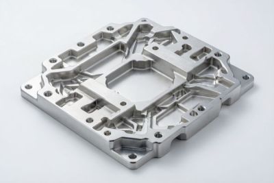
If you are specifying an RF enclosure, a base-station housing, or a precision connector, the metal box in your Bill of Materials is not just a container. It is part of the circuit. The seam, the wall thickness, the flatness of the mating face, and the finish on the inside surface all decide whether your product passes EMC on the first try or comes back from the test lab with a failure you cannot easily explain. Most sourcing decisions for communication enclosures are still made on price per kilogram, and that is exactly why so many programs slip their certification date.
This guide is written the way an engineer would talk to a colleague who is about to place the order. We walk through what a spec sheet actually tells you, where tolerance meets signal integrity in connector machining, how fin geometry controls a CNC heat sink, why your aluminum box leaks RF, how to choose between 6061 and 7075, and when CNC aluminum beats molded plastic. We keep it concrete, with the numbers buyers and test labs care about.
Along the way we flag the questions you should put to any shop on your shortlist, and the mistakes we see most often at the sourcing stage. If you want a second opinion on a drawing, our team at LusterControl (Dongguan Licun Technology Co., Ltd.) will run a free DFM review on your electronic housings or connector parts before you commit to tooling.
Table of Contents
- 1. Why Sourcing Communication Enclosures Demands More Than a Cheap Quote
- 2. Electronic Housings 101: Reading the Spec Sheet Like an Engineer
- 3. Connector Machining: The Tolerances Behind Signal Integrity
- 4. CNC Heat Sinks: How Fin Geometry Lowers Thermal Resistance
- 5. EMI Shielding: Why Your Aluminum Box Leaks RF (and How to Seal It)
- 6. Aluminum CNC Machining: Choosing 6061 vs 7075 for Enclosures
- 7. Communication Enclosures vs Molded Plastic: A 2026 Buyer's Comparison
- 8. A Buyer's Checklist for Sourcing Electronic Housings and Connectors
- 9. Common Sourcing Mistakes for Connector Machining and Electronic Housings
Electronics&Communication AI part image
Why Sourcing Communication Enclosures Demands More Than a Cheap Quote
The cheapest quote is rarely the cheapest outcome when the part has to pass EMC.
A communication enclosure lives in a hostile electrical environment: nearby transmitters, switching power supplies, and fast digital edges that throw harmonics everywhere. A gap at a seam, a poorly grounded lid, or a connector that sits a few microns proud of the panel becomes an antenna you never intended to build. At the test lab, that shows up as radiated emission over the limit, and the fix is rarely a software change.
What actually fails at the test lab
- EMI leakage through an unsealed lid seam or a poorly located gasket groove.
- Thermal shutdown because the CNC heat sink was optimized for looks, not for airflow and conduction.
- Connector misalignment where the milled face drifts by more than the mating tolerance, forcing field rework.
- Poor grounding because the conductive path from lid to chassis was interrupted by paint or anodize.
- Finish-driven corrosion on the inside surface that degrades shield performance over time.
The good news is that a disciplined supplier makes all of this boring. Predictable wall thickness, verified flatness, documented passivation, and a grounding strategy designed in from the start. That is what you are really buying when you source communication enclosures - not kilograms of aluminum.
Electronics&Communication AI part image
Electronic Housings 101: Reading the Spec Sheet Like an Engineer
Most spec sheets tell you what the part is made of, not what it will do in your system.
When a supplier hands you a drawing for electronic housings, the lines that matter for performance are rarely the bold ones. Material grade, wall thickness, and finish get the headline; shield performance, flatness, and grounding features get a footnote if they get anything at all. Read the sheet the way the test lab will read your product.
Terms you should see on every drawing
- EMI / RFI
- Electromagnetic / radio-frequency interference - unwanted energy your enclosure must contain or block.
- Insertion loss
- The signal power lost as it passes through a connector or filter; tight tolerance protects it.
- IP rating
- Ingress protection against dust and water - driven by seams, gaskets, and lid fit.
- Grounding continuity
- A low-impedance path from the lid to the chassis so the shield actually works.
- Wall thickness
- Sets stiffness, shielding mass, and how much you can machine away for features.
The numbers that actually matter
| Spec line | What buyers assume | What it really controls |
|---|---|---|
| Material: 6061-T6 | 'Aluminum is aluminum' | Machinability, corrosion, and how thin you can go safely |
| Wall: 1.5 mm | 'Thicker is stronger' | Stiffness vs weight vs heat-sink volume available |
| Flatness: 0.05 | 'Close enough' | Lid seal integrity and EMI gasket compression |
| Finish: anodized | 'Looks finished' | Surface insulation that can break grounding if not masked |
| Tolerance: ±0.1 | 'Standard precision' | Whether the connector seats without rework |
We machine electronic housings for consumer-electronics and appliance brands such as De'Longhi, Donlim, and Breville, where the same discipline - tight tolerance, clean finish, consistent batches - is what keeps their lines running. The communication-enclosure logic is the same, just with EMC added to the checklist.
Connector Machining: The Tolerances Behind Signal Integrity
A connector is where mechanical tolerance becomes electrical performance.
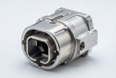
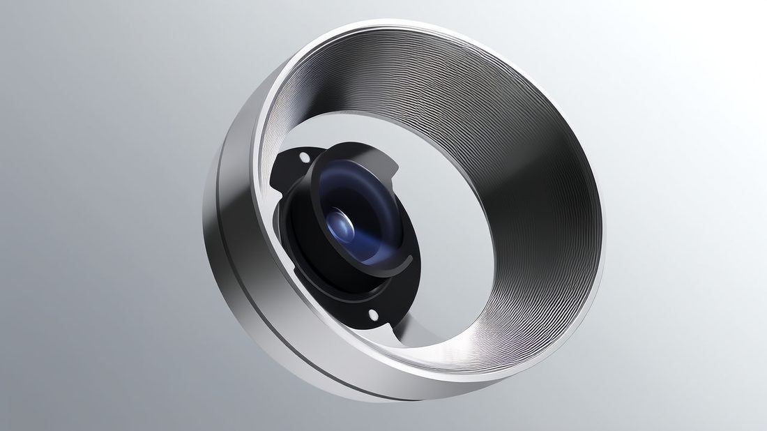
In RF and high-speed links, the connector is the single most tolerance-sensitive component in the chain. The pin position, the dielectric seat, and the outer-shell fit decide return loss and crosstalk long before the signal reaches the board. Connector machining is therefore less about hitting a number and more about holding that number across every cavity in every lot.
Where tolerance meets signal
| Feature | Typical tolerance we hold | Why it matters for RF |
|---|---|---|
| Pin / contact position | ±0.005 mm | Phase alignment and return loss |
| Shell outer diameter | ±0.01 mm | Fit into the panel and shield continuity |
| Seat flatness | ±0.01 mm | Even dielectric compression, no air gap |
| Thread form / pitch | ISO 2 / 3A | Engagement torque and repeatable seating |
| Wall between cavities | ±0.02 mm | Crosstalk isolation between channels |
Pros
- Predictable insertion loss
- Lower field rework
- Cleaner EMC outcomes
Cons
- Tight tolerance costs more to hold
- Needs CMM verification, not eyeballing
- Not every feature needs it
The right shop will tell you which tolerances on your connector actually protect signal integrity and which are just costing you money. That honesty is a qualification signal in itself - the one who tightens everything blindly is the one who quotes high and still ships late.
Electronics&Communication AI part image
CNC Heat Sinks: How Fin Geometry Lowers Thermal Resistance
A heat sink is not a block with ribs. It is a carefully balanced thermal path.
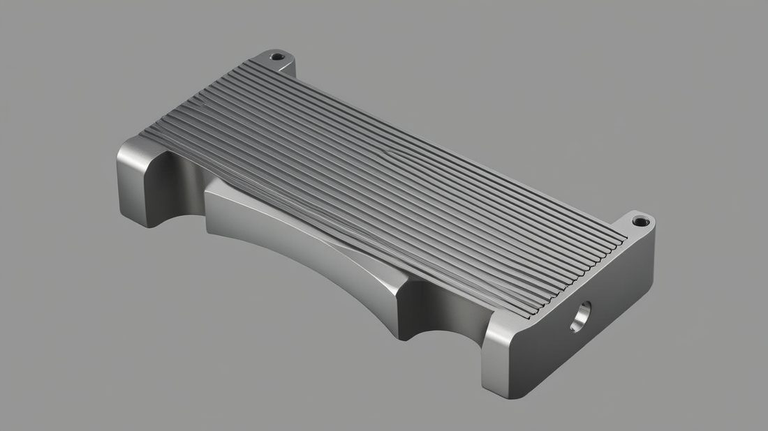
Communication gear runs hot, and hot silicon drifts, loses linearity, and eventually shuts down. A CNC heat sink moves heat from the device to the air, and its performance is set by three levers you control at the drawing stage: the material, the fin geometry, and the flatness of the base that meets the device.
Three levers you control
- Pick the base material - aluminum 6061 conducts well and machines cleanly; copper conducts better but is heavier and pricier.
- Set the fin pitch - too tight and airflow stalls, too wide and you lose surface area; there is a sweet spot per your fan or natural convection.
- Hold the base flat - a base that is not flat traps an air film at the interface, and air is a terrible conductor.
- Consider skived or bonded fins only if volume and performance truly demand it; machined fins are simpler and fully traceable.
| Fin pitch | Relative thermal resistance | When it wins |
|---|---|---|
| 0.5 mm (dense) | Higher (air stalls) | Only with forced high-velocity airflow |
| 1.5-2.0 mm (balanced) | Lowest for most apps | Natural convection and modest fans |
| 4.0 mm+ (sparse) | Higher (less area) | Very low airflow, cost-driven designs |
| Base flatness ±0.02 mm | Removes interface air gap | Every bonded device |
We machine CNC heat sinks alongside the enclosures they live in, so the sink, the wall, and the mounting face can be dialed in as one thermal system rather than three separate purchase orders that never quite line up.
EMI Shielding: Why Your Aluminum Box Leaks RF (and How to Seal It)
Aluminum conducts, but conduction alone does not make a shield.
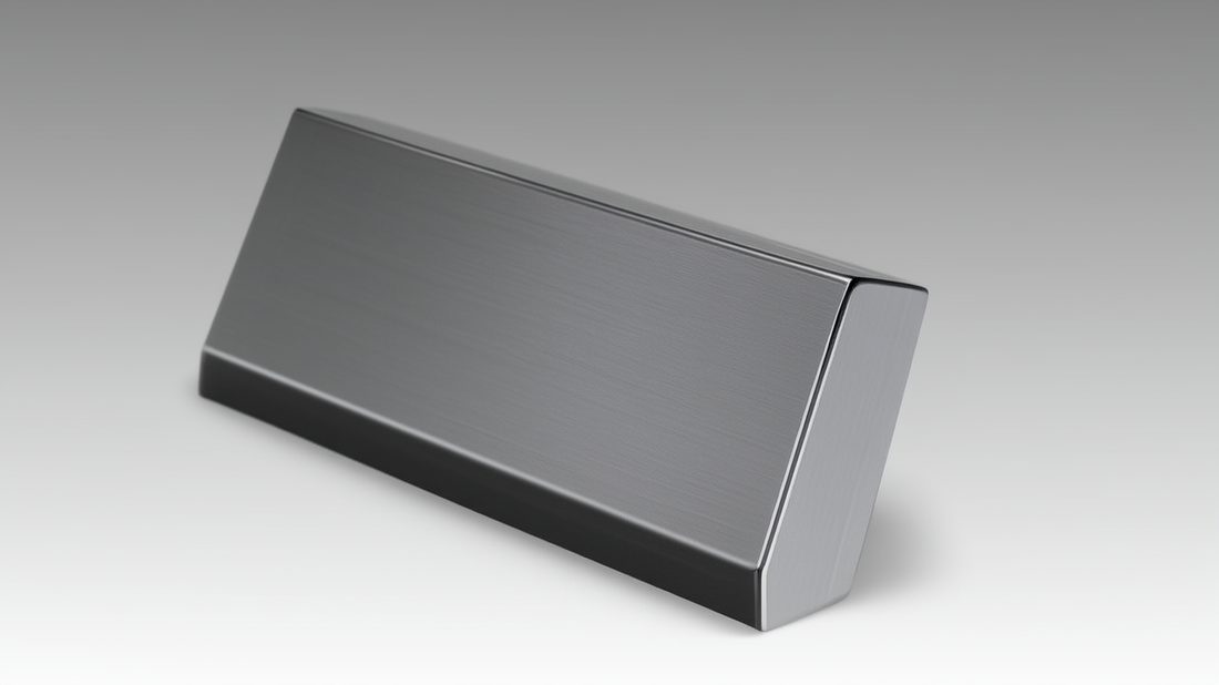
A solid aluminum wall is a good RF shield in theory. In practice your enclosure has a lid, vents, and cable openings, and each one is a potential leak. EMI shielding is the sum of how well every seam and opening is treated, not the bulk conductivity of the metal.
The three leakage paths
- Seams and lid lines - the number-one leak; solved by gasket grooves, conductive gaskets, or finger stock at the joint.
- Vents and displays - necessary for cooling and use, solved by vented EMI filters or shielded windows.
- I/O and connector openings - solved by panel-mounted connectors with conductive shells that land on the shield.
| Shielding method | Typical attenuation | Trade-off |
|---|---|---|
| Conductive gasket at seam | 40-60 dB | Cost and compression design needed |
| Finger stock | 50-70 dB | Wear over many open/close cycles |
| Conductive coating / paint | 20-40 dB | Easily broken by scratches; not a sole fix |
| Machined-in shield cans | 60+ dB | Internal volume consumed |
We approach EMI shielding as a grounding problem first and a material problem second, which is why our aluminum CNC machining includes masking and passivation steps that keep the conductive path intact instead of painting over it.
Electronics&Communication AI part image
Aluminum CNC Machining: Choosing 6061 vs 7075 for Enclosures
The grade you pick sets what you can machine, how thin you can go, and what it costs.
For communication enclosures, 6061 and 7075 are the two workhorses, and the choice is not 'stronger is better.' It is a balance of machinability, corrosion behavior, wall thickness, and budget. Getting it wrong either over-spends on material or under-delivers on stiffness.
Grade comparison
| Property | 6061-T6 | 7075-T6 |
|---|---|---|
| Tensile strength | Medium (~310 MPa) | High (~570 MPa) |
| Machinability | Excellent | Good, more tool wear |
| Corrosion resistance | Very good | Lower, needs protection |
| Thin-wall capability | Great for light enclosures | Stiffer at same wall |
| Relative cost | Lower | Higher |
| Best use | Most comms enclosures | Rugged / structural mounts |
Finish and corrosion control
After aluminum CNC machining, we control corrosion and keep the shield path clean with passivation to ASTM A967, which restores the protective oxide and prevents the creep corrosion that quietly degrades RF performance in humid service. For appearance and abrasion, anodize is added only where it will not break grounding.
The best enclosure grade is the one that meets stiffness and corrosion needs with the least cost and the most repeatable machining - not the one with the biggest strength number.
Communication Enclosures vs Molded Plastic: A 2026 Buyer's Comparison
CNC aluminum is not always the answer, but it is the safe default for low-to-mid volume RF.
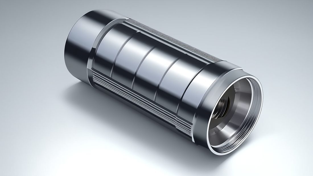
Buyers often assume molded plastic is automatically cheaper. For very high volumes it usually is, because the tooling amortizes. But for communication enclosures where EMI, wall tolerance, and fast design changes matter, CNC aluminum is frequently the lower-risk path - especially below roughly 50,000 units a year.
| Factor | CNC aluminum enclosure | Molded plastic enclosure |
|---|---|---|
| Tooling / NRE | None or minimal | High injection mold cost |
| Lead time to first part | Days to weeks | Weeks to months for tooling |
| EMI shielding | Excellent, built in | Poor, needs conductive fill / coating |
| Design changes | Easy, just edit CAM | Costly mold revision |
| Volume sweet spot | Prototype to ~50k/yr | 100k+/yr |
| Thermal conduction | Good (acts as sink) | Poor, needs separate sink |
Choose aluminum CNC machining if
- You need EMI shielding without bolting on coatings and fillers.
- Your annual volume is under about 50,000 and tooling cost would dominate.
- The design is still moving and you cannot afford a mold revision cycle.
- The enclosure itself must help dissipate heat from internal devices.
Choose molded plastic if
- Volume is high and stable, so the mold pays for itself.
- EMI is handled by a separate shielded can or conductive cage inside.
- Weight and part count reduction outweigh the shielding trade-off.
- The geometry is frozen and unlikely to change for years.
For most communication programs we see, the honest recommendation is CNC aluminum through qualification and ramp, then a mold only if volume and stability justify it. You can read more about our approach to communication enclosures and related programs on our blog.
Electronics&Communication AI part image
A Buyer's Checklist for Sourcing Electronic Housings and Connectors
Copy this and send it to every shop on your shortlist. The answers will sort them fast.
- Can they state shield-performance intent (seam treatment, grounding path), not just 'we machine aluminum'?
- Do they hold and verify ±0.005 mm on connector and critical enclosure features with CMM data?
- Will they provide first-article inspection (FAI) and in-process SPC on every lot?
- Can they passivate to ASTM A967 and mask anodize so grounding stays intact?
- Do they machine 6061 and 7075 regularly and advise which grade fits your part?
- Can they deliver the enclosure and the CNC heat sink as one coordinated system?
- Do they support prototype to production without re-qualifying the process?
- Do they answer engineering questions with specifics, not sales language?
A supplier that clears all eight is rare and worth keeping. One that stumbles on grounding, finish verification, or tolerance proof should not be on an RF program. When you are ready, send your drawing to our connector machining and enclosure team for a free DFM review.
Common Sourcing Mistakes for Connector Machining and Electronic Housings
Most EMC and fit failures were decided at the sourcing stage, not on the shop floor.
- Chasing the lowest per-kilo price and discovering the saving evaporates in test-lab rework and delay.
- Treating EMI shielding as a coating spec instead of a grounding and seam design problem.
- Skipping first-article inspection to 'save time' - it is the cheapest insurance you have.
- Leaving tolerances as 'standard precision' on the drawing, then arguing about fit after shipment.
- Ignoring thermal design until the prototype overheats, then reshaping the heat sink under panic.
- Forgetting corrosion control - an unpassivated inside surface degrades shield performance in humid service.
None of these are deep technical mysteries. They are habits - and the right supplier for your electronic housings and connectors should make the correct habit the easy default. Dongguan Licun Technology has built that habit across 15 years and 60+ machines, and our annual output now exceeds 20 million RMB serving brands that cannot afford a field failure.
Electronics&Communication AI part image
Electronics&Communication AI part image
Electronics&Communication AI part image
Electronics&Communication AI part image
FAQ: electronic housings & Electronics&Communication Buyer Questions
A: We routinely hold ±0.005 mm on critical diameters, pin positions, and connector cavities, and ±0.01 mm on flatness and feature position, verified by CMM rather than estimated. Less critical features are opened up to save cost unless they affect fit or shielding.
A: A solid aluminum wall shields well by itself, but real enclosures have seams, vents, and I/O openings that leak. True shielding comes from designing the grounding path and seam treatment (gasket grooves, finger stock, panel-mounted shielded connectors), with conductive coating only as reinforcement - never as the sole fix.
A: 6061-T6 is the default for most communication enclosures: excellent machinability, good corrosion resistance, and easy thin-wall work. Choose 7075-T6 only when you need higher strength or stiffness at the same wall, accepting higher cost and more corrosion protection effort.
A: ASTM A967 passivation restores and enhances the aluminum oxide layer that resists corrosion. For electronic housings it prevents creep corrosion that would otherwise degrade shield performance in humid or outdoor service, and it keeps the conductive grounding path clean when applied with correct masking.
A: Choose CNC aluminum for prototype through roughly 50,000 units per year, for fast design changes, and whenever built-in EMI shielding and heat conduction matter. Choose die-cast or molded plastic only at very high, stable volumes where tooling amortizes and shielding is handled separately inside.
A: Yes. We run first-article inspection on new designs, support low-volume custom runs, and scale to monthly production while keeping the same documented process and traceability - so your program can grow from qualification to volume without re-qualifying the source. Learn more on our <a href='https://www.lustercontrol.com/about.htm'>about page</a>.
Ready to qualify a supplier for your communication enclosures or connector parts? Send us your drawing and we will return a free DFM review with tolerance, shielding, and finish recommendations - no obligation, just a clear engineering answer from LusterControl.
Request a Free CNC Quote