Sourcing Lightweight UAV Arm Tubes: Drone Buyer's Guide (2026)
If you have ever watched a heavy-lift drone dip a wing on takeoff, the cause is rarely the flight controller - it is the arm. The arm tube is the long, slender boom that carries the motor and propeller out from the body, and its job is to hold the thrust line exactly where the software expects it. The moment that tube twists or sags under load, the controller burns energy fighting a geometry problem it was never designed to solve.
This guide is written for the engineer or procurement lead who is about to send an arm-tube drawing to a machine shop. We walk through when 5-axis CNC machining actually earns its keep on long tubes, how material choice between TC4 titanium and aerospace-grade aluminum changes your stiffness-to-weight math, and which tolerances on a UAV structural components program are worth paying for versus which ones just inflate the quote.
We are Dongguan Licun Technology Co., Ltd. (brand LusterControl), a South China source factory focused on precision CNC and stainless mirror finishing since 2015. Our floor runs 60 CNC machines across a 4,000 m2 plant (expanded in 2026) with monthly output around 500k parts, and one of our earliest drone customers placed a first production order worth 1.2 million RMB. The numbers and trade-offs below are the ones we argue through with customers before the first chip is cut - not catalog fluff.
Table of Contents
- 1. How 5-Axis CNC Machining Builds Straight, True UAV Arm Tubes
- 2. Designing Lightweight CNC Machining of UAV Arm Tubes That Don't Flex
- 3. UAV Structural Components: Why Arm Tubes Are Flight-Critical
- 4. Choosing Aerospace-Grade Aluminum for UAV Arm Tubes
- 5. TC4 Titanium Machining for High-Strength Drone Arm Tubes
- 6. Drone Motor Mounts vs Arm Tubes: Where to Spend Tolerance Budget
- 7. Lightweight CNC Machining: Titanium vs Aluminum for Arm Tubes
- 8. Common Sourcing Mistakes in UAV Structural Components
UAV/Drone AI part image
How 5-Axis CNC Machining Builds Straight, True UAV Arm Tubes
On a long tube, straightness and end-squareness beat diameter every time.
An arm tube is a cantilever: one end bolted to the body, the other carrying a motor pod that can weigh 200 g to several kilograms and spins at thousands of rpm. The properties that decide whether your drone flies level are the straightness of the tube and the squareness of the motor-mount face to the tube axis - not the bore diameter. Cutting those on a 3-axis machine means flipping and re-clamping a long, floppy part two or three times, and every re-clamp risks a datum shift that shows up as a tilted motor.
5-axis CNC machining lets us hold the tube on one datum and rotate the head around it, machining the end fittings, motor bosses, and wire-passage features in a single setup. Because the coordinate system never moves, we hold positional accuracy to +/-0.005 mm along the full length and keep the motor face perpendicular to the axis within 0.02 mm. For a customer running an X8 heavy-lift layout, that single-setup consistency removed a hand-lapping step they used to do after every batch.
Why straightness, not diameter, drives flight
A 0.02 mm diameter error on a 16 mm tube is invisible in the air. A 0.1 mm/m bow, or a motor face 0.03 mm out of square, tilts the thrust vector and the flight controller pays for it in current draw and vibration. We therefore tolerance the tube on three relationships: end-to-end straightness, face-to-axis perpendicularity, and the true position of the motor-pilot bore - and we relax every cosmetic dimension to commercial limits to keep cost sane.
- End-to-end straightness: 0.1 mm per meter typical, 0.05 mm for survey-grade
- Motor-face perpendicularity to axis: 0.02 mm
- Pilot bore true position: +/-0.03 mm
- Wall thickness minimum: 0.8 mm aluminum, 0.6 mm titanium
- Corner radii: R0.5 minimum to avoid stress risers
| Factor | 3-axis (multi-setup) | 5-axis (single setup) |
|---|---|---|
| Datum shifts on a long tube | 0.02-0.05 mm per re-clamp | None after first clamp |
| Straightness control | Hard to hold over length | Held to 0.05-0.1 mm/m |
| Best for | Short fittings, spacers | Full-length arm tubes, pods |
| Our accuracy | +/-0.01 mm | +/-0.005 mm |
UAV/Drone AI part image
Designing Lightweight CNC Machining of UAV Arm Tubes That Don't Flex
Flexural rigidity scales with wall thickness - and so does your crash risk.
Lightweight CNC machining of an arm tube is fundamentally a stiffness-per-gram problem, and the lever you have is wall thickness. For a thin-walled tube, bending stiffness scales roughly with the cube of the wall, so going from 0.8 mm to 1.2 mm wall can nearly double rigidity for a modest mass penalty. Shaving the wall to 0.5 mm to save grams is the single most common way we see a prototype that looks great on paper fold on its second hard landing.
We co-develop the wall schedule with the customer before machining: thicker near the body and motor bosses where bending moment peaks, thinner in the mid-span where it only carries shear. This 'variable wall' approach trims mass where it does not matter and banks rigidity where it does, and it is far cheaper than switching to titanium later.
A five-step wall-thickness checklist
- List the bending and torsional loads at hover and at max thrust
- Set a wall minimum of 0.8 mm (alu) or 0.6 mm (Ti) at any point
- Thicken 20-30% at body root and motor boss
- Simulate first-mode frequency after each pocket change
- Verify a real part on a deflection rig before sign-off
UAV Structural Components: Why Arm Tubes Are Flight-Critical
The arm is the only thing between a spinning rotor and your airframe.
Among all UAV structural components, the arm tube is unusual because it is loaded in three ways at once: bending from the motor thrust, torsion from propeller torque, and axial pull on hard acceleration. A frame plate might see mostly in-plane load; an arm tube sees all of it along its length. That is why we treat arm tubes as flight-critical parts, not cosmetic booms, and inspect them like the links they are.
- Arm tube
- The slender boom extending from the airframe to the motor pod; carries thrust, bending, and torsion.
- Motor pod / mount
- The CNC-machined end fitting that clamps the tube and registers the motor pilot.
- Cantilever
- A beam fixed at one end and loaded at the other - the load case that defines arm-tube stress.
- True position
- The allowable deviation of a feature from its ideal coordinate, measured from a datum.
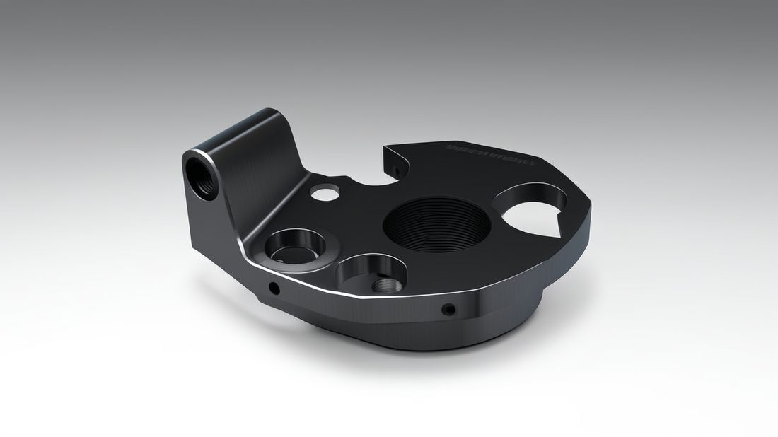
Because the tube is a cantilever, the stress peaks at the body root and at the motor boss. Those are exactly the zones where we add material and where we concentrate the tolerance budget. The mid-span can be lightened aggressively because its bending moment is lowest - a fact many first-time designers miss and over-build.
| Load type | Peaks at | What we spec |
|---|---|---|
| Bending (thrust) | Body root, motor boss | Wall +0.2-0.3 mm, R0.5 corners |
| Torsion (prop torque) | Full length | Closed or thick-wall section |
| Axial pull | Body root fasteners | Symmetric bolt pattern, pilot fit |
| Vibration | Motor face | Ra 1.6 um seat, resonance above band |
UAV/Drone AI part image
Choosing Aerospace-Grade Aluminum for UAV Arm Tubes
6061 for most arms, 7075 where yield strength earns its keep.
Aerospace-grade aluminum is the default for the majority of UAV arm tubes because it is cheap, dimensionally stable, and easy to hold to tight tolerances. 6061-T6 covers most arms, clamps, and plates; 7075-T6 steps in where yield strength matters and you can manage its lower corrosion resistance with anodize. For a typical multirotor arm, 6061 is the right answer 80 percent of the time.
Anodize changes your tolerances
We anodize most aluminum arm tubes - Type II for a durable matte finish that hides handling marks, Type III hard coat where the clamping face sees abrasion. Anodize adds a few microns; a Type III coating can close a 0.005 mm slot. We machine the motor bore undersize and let the coating bring it to nominal, so the press-fit motor pilot seats correctly. Miss that and the motor binds on the line.
| Alloy | Use it for | Watch out for |
|---|---|---|
| 6061-T6 | Standard arms, clamps, plates | Lower strength vs 7075 |
| 7075-T6 | High-stress arms, heavy-lift | Corrosion; anodize required |
| 2024-T3 | Fatigue-critical booms | Poor corrosion, rare in UAV |
Pros
- Low cost and fast cycle time
- Excellent dimensional stability
- Easy to hold +/-0.005 mm
- Wide anodize finish options
Cons
- Lower specific strength than titanium
- 7075 needs corrosion protection
- Soft face scratches without coating
TC4 Titanium Machining for High-Strength Drone Arm Tubes
Titanium is not 'better aluminum' - it is a different engineering deal.
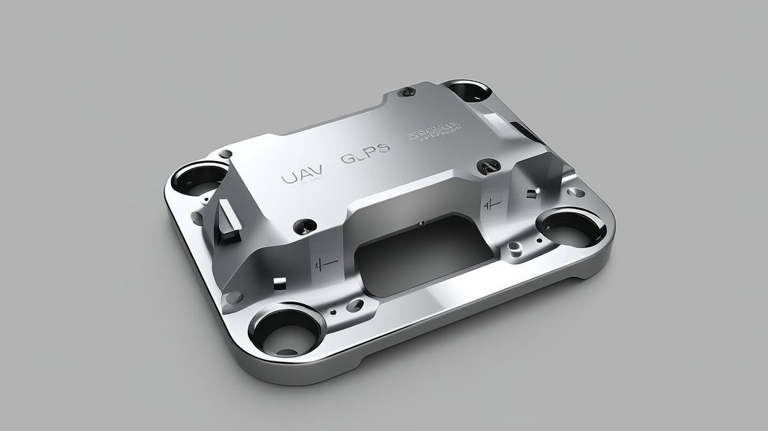
TC4 titanium machining pays off only when strength-to-weight or corrosion resistance genuinely drives the design. TC4 (Grade 5, Ti-6Al-4V) sits at 4.43 g/cc but a modulus near 114 GPa and roughly double the yield of 7075 aluminum. For a bending-limited arm, you can use less titanium than aluminum and come out lighter - which is why high-end and heavy-lift programs reach for it.
The cutting recipe we machine titanium by
Titanium conducts heat poorly and work-hardens if the tool rubs, so our recipe is low radial engagement (about 0.5 mm or 8 percent of cutter diameter), sharp AlTiN inserts, through-spindle coolant, and conservative surface speeds near 30-50 m/min. We leave 0.1 mm for a finishing pass and hold the contour to +/-0.01 mm. After machining we passivate per ASTM A967 so the surface resists fingerprint corrosion during handling.
- Confirm material cert (ASTM B348 Grade 5 / TC4)
- Agree on coolant and ASTM A967 passivation up front
- Define free-state vs clamped tolerances
- Plan fixture relief for thin walls
- Decide final Ra on visible faces (Ra 0.8 um typical, Ra 0.2 um mirror on request)
UAV/Drone AI part image
Drone Motor Mounts vs Arm Tubes: Where to Spend Tolerance Budget
Both are structural, but only one decides your thrust line.
Buyers often lump drone motor mounts and arm tubes into one 'structure' bucket and demand the same tight tolerance on both. They are not the same. The motor mount sets the thrust-line angle and the pilot fit that the rotor spins on; an error there shows up immediately as vibration. The arm tube sets where the mount sits in space; its critical features are straightness and end-squareness, not a tight bore.
Spend tight tolerance where the flight depends on it
We concentrate the tolerance budget on the motor-mount pilot and bolt circle, and on the arm-tube face-to-axis perpendicularity. The tube's outer diameter, surface finish away from the seat, and length get commercial tolerances. This 'tolerance triage' is how we keep a flight-critical part affordable.
| Feature | Tight tolerance? | Why |
|---|---|---|
| Motor pilot bore | Yes (+/-0.03 mm) | Rotor spins on it |
| Bolt-circle true position | Yes (+/-0.03 mm) | Even clamp load |
| Arm face-to-axis squareness | Yes (0.02 mm) | Sets thrust line |
| Tube outer diameter | No (commercial) | Cosmetic / clearance |
| Mid-span wall | No (range) | Low bending moment |
Lightweight CNC Machining: Titanium vs Aluminum for Arm Tubes
Pick the material from the failure mode, not the spec sheet.
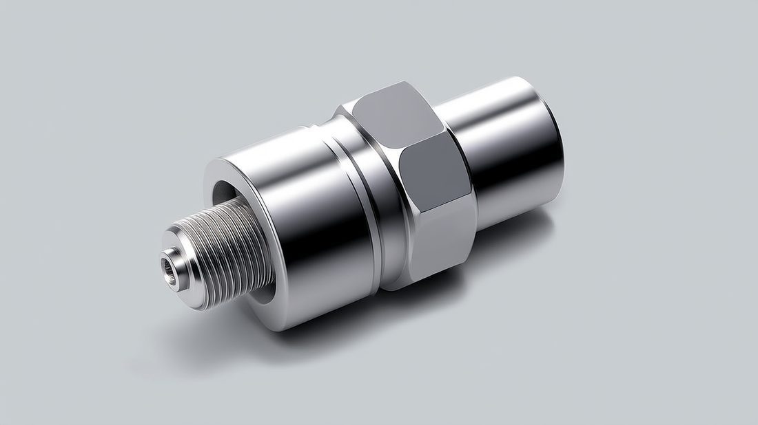
Lightweight CNC machining really means stiffness-per-gram. If your arm fails by bending, titanium's higher modulus lets you use less material and come out lighter than aluminum despite being denser. If it fails by local yield at the boss, 7075 aluminum with a thicker wall usually wins on cost. And if corrosion in marine or agricultural spray is the real risk, titanium's no-coating resistance is worth the premium.
| If your limit is... | Choose | Reasoning |
|---|---|---|
| Bending stiffness per gram | TC4 titanium | Higher modulus, less material |
| Local yield at boss | 7075 aluminum | Cheaper, thicken the wall |
| Corrosion (marine/spray) | TC4 titanium | No coating needed |
| Cost and lead time | 6061 aluminum | Fastest, cheapest, stable |
| Fatigue over thousands of cycles | 7075 or TC4 | Avoid 2024 if corrosion exposed |
When you are ready to commit a material, send the drawing to a shop that can machine both and give you an honest costed comparison. A free DFM review from our engineering team will flag whether your arm is bending-limited or yield-limited before you pay for titanium you may not need.
UAV/Drone AI part image
Common Sourcing Mistakes in UAV Structural Components
Most arm-tube problems are bought, not machined.
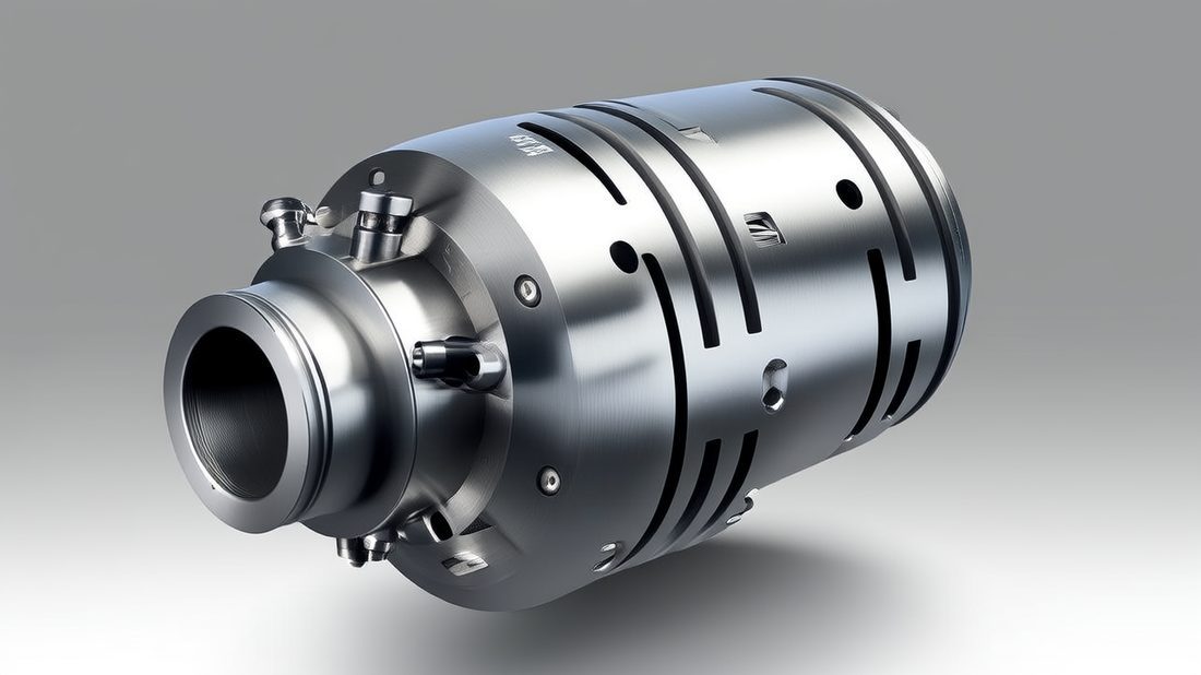
Sourcing UAV structural components is less about finding a cheap machine and more about finding a shop that understands flight-critical intent. The mistakes below are the ones we see most often from first-time drone buyers, and every one of them is visible in the drawing or the quote before a part is cut.
- Uniform thin wall chasing a mass target, then root cracks on landing
- Specifying bare-metal tolerances on a part that will be anodized
- Demanding 5-axis on a part that a 3-axis can do in one cheap setup
- Forgetting free-state vs clamped form on thin-walled tubes
- No material cert or heat-lot traceability required
- Asking for a photo instead of a CMM first-article report
- Ask for the cert stack: ISO 9001 minimum, IATF 16949 or AS9100-aligned discipline a plus
- Require material certs traceable to the heat lot
- Confirm single-setup 5-axis capability, not 3-axis with re-fixturing
- Get a CMM first-article report with full datum references
- Agree coated vs bare tolerances before quoting
- Verify lot traceability and a real rework path
UAV/Drone AI part image
UAV/Drone AI part image
UAV/Drone AI part image
UAV/Drone AI part image
FAQ: UAV structural components & UAV/Drone Buyer Questions
A: Yes, on a single setup. The key is never releasing the datum; with the tube clamped once and the axes rotating, we hold positional accuracy to +/-0.005 mm along the length and keep the motor face perpendicular to the axis within 0.02 mm. Thin walls need a tensioning fixture so the part does not spring during the finishing pass.
A: Only when stiffness-to-weight or corrosion resistance drives the design. Titanium's higher modulus lets you use less material for a bending-limited arm, but cycle time runs 2-3x aluminum. For most arms, 6061 or 7075 aluminum is the better value; titanium wins for heavy-lift or marine-corrosion programs.
A: We machine the bore undersize by the anticipated coating thickness - a few microns for Type II, more for Type III hard coat - so the finished, coated bore lands at nominal. Designing to the bare condition is the classic mistake that causes binding on the assembly line.
A: Keep a minimum of 0.8 mm in aluminum and 0.6 mm in titanium at every point, then thicken 20-30 percent at the body root and motor boss where bending moment peaks. Mid-span can be lightened aggressively because its moment is lowest.
A: Yes. We supply material certs traceable to the heat lot, a CMM first-article report with full datum references, in-process gauging for batch parts, and lot-level traceability from raw bar to finished component. ISO 9001 certified, ISO 13485 completed, IATF 16949 in application.
A: Single prototypes are routine, and our floor is built for both small custom batches and volume - around 500k parts a month across 60 machines. For a dedicated arm program we typically qualify at low volume, lock the CMM data, then scale.
Send us your arm-tube or motor-mount drawing and get a free DFM review - we will flag whether your part is bending-limited or yield-limited, where your tolerance budget should go, and the honest material call between TC4 titanium and aerospace-grade aluminum. Let's cut the first article.
Request a Free CNC Quote