Thermal Management in Energy Storage: Machined Baseplates Explained (2026)
If you are specifying an energy storage system in 2026, the question that decides whether your pack lasts three years or ten is not the cells - it is the heat. Every charge and discharge cycle pushes thermal energy into the enclosure, and unless that heat has a clean path out, cells age faster, capacity fades, and in the worst case you are one hot spot away from thermal runaway. As an engineer or buyer, the part you should be losing sleep over is the quiet one underneath everything: the machined baseplate.
This guide walks through thermal management the way we approach it on the shop floor - from why a few degrees matter, to how battery box parts and copper bus bars are actually machined, to the copper-vs-aluminum decision that changes your pack weight and cost. We keep it practical and plain, the way an engineer would explain it to a colleague who has to sign the purchase order.
Along the way we cover the tolerances that keep contact resistance down, the material data you should demand from any supplier, a buyer's checklist you can copy, and the mistakes we see most often when teams source energy storage components for the first time. The goal is simple: help you specify a cooled, reliable pack instead of an expensive space heater.
Table of Contents
- 1. What Thermal Management Really Means in Energy Storage Systems
- 2. Why Energy Storage Components Live or Die by Heat
- 3. Battery Box Parts: The Structural Heart of Pack Cooling
- 4. Copper Bus Bars: Carrying Current Without Cooking the Pack
- 5. CNC Power Parts: Machining the Current-Carrying Geometry
- 6. Aluminum CNC Machining for Lightweight Baseplates
- 7. Copper Bus Bars vs Aluminum Baseplates: Which Material Wins for Your Pack
- 8. A Sourcing Checklist for Energy Storage Components and Machined Baseplates
- 9. Common Mistakes Buyers Make with Battery Box Parts and CNC Power Parts
Energy Storage AI part image
What Thermal Management Really Means in Energy Storage Systems
Thermal management is not a fan and a hope. It is a designed path for heat to leave the pack.
Thermal management in an energy storage system is the disciplined control of where heat is generated, how it moves, and where it ends up. Cells generate heat during both charge and discharge. That heat has to travel from the cell surface, through a bonded interface, into a machined baseplate, and then into a cold plate or liquid loop. If any step in that chain has a gap, an air pocket, or a rough surface, the heat piles up where you cannot see it.
The three jobs a baseplate has to do
- Spread heat - pull localized cell hot spots across a wide, flat metal surface so no single point cooks.
- Conduct heat - move it efficiently into the cooling plate below via high-conductivity material and a clean, gap-free interface.
- Structure the pack - carry the mechanical load of cells, bus bars, and brackets while staying dimensionally stable over temperature swings.
- Thermal management
- The engineered control of heat generation, conduction, and removal inside a battery or power system.
- Baseplate
- The flat machined plate that bonds cells to the cooling loop and carries pack structure.
- Thermal resistance
- A measure of how hard heat must work to cross an interface; lower is better.
- Thermal runaway
- An uncontrolled, self-heating failure that can cascade across a whole pack.
A baseplate that is flat and smooth to Ra 0.2 µm (what we call 8K mirror) lets the thermal interface material do its job instead of fighting air gaps. That is the difference between a pack that stays at 35 C and one that creeps toward 50 C under load.
Energy Storage AI part image
Why Energy Storage Components Live or Die by Heat
Every 10 C of cell temperature roughly halves the path to failure. Heat is not cosmetic.
The reason thermal management dominates pack design is brutal arithmetic. Lithium cells age faster as they get hotter, and the relationship is steep. A pack that runs 10-15 C cooler can deliver a large multiple of cycle life. For an energy storage components buyer, that translates directly into warranty exposure and replacement cost - not a lab curiosity.
What temperature does to a pack over its life
| Cell surface temp | Typical effect on life and safety |
|---|---|
| 25-35 C | Optimal band; full rated cycle life, stable capacity. |
| 35-45 C | Noticeable capacity fade; accelerated seal and electrolyte aging. |
| 45-55 C | Rapid degradation; much shorter service interval. |
| 55 C+ | Runaway risk rises sharply; pack-level safety concern. |
This is why the mechanical parts - baseplates, brackets, and the boxes that hold cells - are treated as thermal parts, not just structural ones. A battery box part that warps 0.05 mm under thermal cycling opens a gap that the cooling system can never close. Design the heat path first; bolt the structure around it.
Battery Box Parts: The Structural Heart of Pack Cooling
The box is not a container. It is the platform that keeps every cell in contact with the cold path.
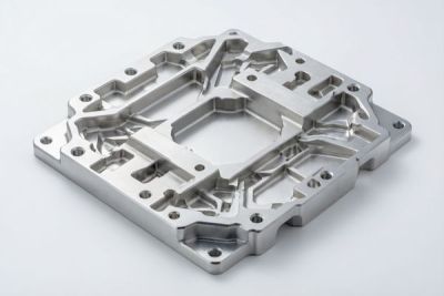
Battery box parts are the machined housings, trays, and end plates that hold cells in place and define the cooling interface. In a liquid-cooled pack they are often the part the cold plate bolts directly to, so their flatness and stiffness decide whether the thermal interface material actually touches the cells. Get this wrong and no amount of pump flow saves you.
How a battery box part is built on our floor
- Rough machine the tray and ribs from aluminum plate, leaving stock for stress relief.
- Stress-relieve so the part does not move after you cut the final features.
- Finish-mill the cooling-face flat to ±0.005 mm so the interface material seats evenly.
- Drill and tap the cooling-channel and mounting features in one setup to protect datums.
- Deburr, clean, and verify flatness and position with CMM before it leaves.
| Feature on a battery box part | Tolerance we hold | Why it matters |
|---|---|---|
| Cooling contact face flatness | ±0.005 mm | Even thermal interface, no hot gaps |
| Cell pocket position | ±0.02 mm | Cells seat consistently, no binding |
| Bolt-hole pattern | ±0.05 mm | Cold plate aligns first time |
| Wall thickness | ±0.1 mm | Stiffness vs weight balance |
Keeping the cooling face flat is the single highest-leverage thing we do on a battery box part. It is also the easiest thing for a low-cost shop to skip, which is why we verify it rather than assume it.
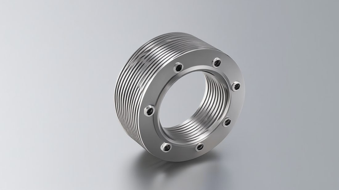
Energy Storage AI part image
Copper Bus Bars: Carrying Current Without Cooking the Pack
A bus bar's job is to move current, not heat. The two are in a constant tug of war.
Copper bus bars are the thick, flat conductors that link cells and modules to the pack terminals. Their purpose is to carry high current with minimal resistive loss - because every watt lost as I-squared-R heat is a watt your cooling system has to remove. Copper's high conductivity lets you keep the bar relatively small while staying cool, which is why it dominates where space is tight.
The numbers that decide copper vs aluminum
| Property | Copper (C1100) | Aluminum (6061) |
|---|---|---|
| Conductivity (IACS) | ~100% | ~40-45% |
| Resistive loss at equal size | Low | 2x higher |
| Weight at equal current | Heavier | Lighter |
| Cost driver | Material price | Volume needed |
| Corrosion handling | ASTM A967 passivation | Anodize / coat |
- Bus bar
- A rigid conductor, usually copper or aluminum, that distributes current within a pack.
- IACS
- International Annealed Copper Standard; a percentage measure of conductivity.
- I-squared-R loss
- Heat generated by current flowing through resistance; the enemy of cool packs.
Copper costs more per kilo, but when you calculate the cooling burden it offloads, it often pays for itself in a smaller thermal system. The right answer depends on your current density and your weight budget - which is exactly the trade we untangle later.
CNC Power Parts: Machining the Current-Carrying Geometry
A power part is only as good as its contact. Tolerances there are thermal tolerances in disguise.
CNC power parts is the umbrella for the machined conductors inside a pack - terminal blocks, bus bar contacts, current sensors housings, and the brackets that hold them precisely where they belong. Their defining requirement is repeatable, low-resistance contact. A loose or misaligned contact drives resistance up, temperature up, and eventually a burn or a drop-out.
Tolerances that keep contact resistance down
| Feature on a CNC power part | Tolerance we hold | Consequence of missing it |
|---|---|---|
| Contact face flatness | ±0.005 mm | Localized hot spot at the joint |
| Bolt-hole position | ±0.02 mm | Contact shifts off-center, resistance rises |
| Plating thickness | ±0.005 mm | Inconsistent interface, corrosion risk |
| Insulator pocket | ±0.03 mm | Clearance or short risk |
Pros
- Predictable, low contact resistance
- Easier automated assembly
- Lower field-failure rate
Cons
- Tight tolerance costs more to hold
- Plating adds a process step
- Inspection time grows
The disciplined move is to tell your supplier exactly which faces are current-carrying and ask for those tolerances in writing. A shop that quotes 'high precision' without naming the feature is not managing your resistance risk.
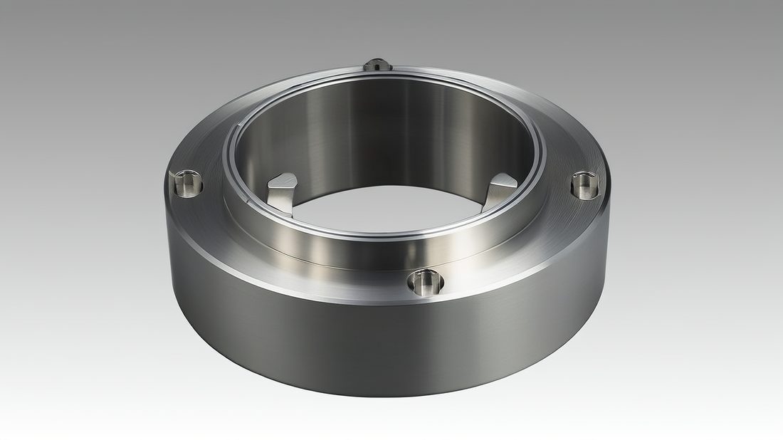
Energy Storage AI part image
Aluminum CNC Machining for Lightweight Baseplates
Aluminum gives you flat, light, conductive - the three things a baseplate wants to be.
Aluminum CNC machining is the default route to a lightweight baseplate. Aluminum conducts heat well, weighs about a third of steel, and machines to a very flat, stable face. For a stationary storage cabinet weight matters less, but for a containerized or mobile unit every kilogram of baseplate is kilograms you cannot spend on cells.
How we machine a flat, thermally stable baseplate
- Select the grade - 6061 for general use, 6082 where strength matters, 7075 where stiffness is critical.
- Rough and leave stock, then stress-relieve to remove internal movement.
- Finish-mill the cooling face to ±0.005 mm flatness and Ra down to 0.2 µm where the interface sits.
- Machine cooling channels or pin fins in the same setup to protect datums.
- Anodize or coat for corrosion protection and to keep the surface stable over cycles.
| Aluminum grade | Strength | Machinability | Best use in a pack |
|---|---|---|---|
| 6061-T6 | Good | Excellent | General baseplates, housings |
| 6082-T6 | Better | Good | Structural trays, ribs |
| 7075-T6 | High | Fair | Stiff brackets, lightweight frames |
Aluminum also plays well with the cold plate above it. Its moderate expansion coefficient and good conductivity make the interface predictable, which is exactly what your thermal model assumed when it promised you 35 C.
Copper Bus Bars vs Aluminum Baseplates: Which Material Wins for Your Pack
This is not a fight. It is a division of labor - copper for current, aluminum for structure and spread.
The copper-vs-aluminum question comes up constantly, and the honest answer is that they are not really competitors. Copper wins where current flows; aluminum wins where you need a large, light, flat surface. A well-designed pack usually uses both - copper bus bars for conduction, aluminum baseplates for structure and spread.
| Factor | Copper bus bar | Aluminum baseplate |
|---|---|---|
| Primary role | Carry current | Spread and remove heat |
| Weight sensitivity | Lower priority | High priority |
| Cost at equal current | Higher material cost | Lower, needs more volume |
| Finish requirement | Plating for contact | Flat + anodize for interface |
| Where it earns its keep | Tight conductor runs | Large cooling face |
Decision table for your pack
| If your priority is... | Choose | Why it wins |
|---|---|---|
| Minimizing conductor heat | Copper bus bars | Lowest I-squared-R loss at given size |
| Cutting pack weight | Aluminum baseplate | A third the density of steel, good conduction |
| Max cooling-face area | Aluminum baseplate | Cheap to machine large, flat, stable plates |
| High current in tight space | Copper bus bars | Small bar still carries the amps cool |
Choose copper if your pack pushes high current through narrow conductor runs and you cannot afford the heat. Choose aluminum if your bottleneck is a large, light, flat cooling surface and weight is on the critical path. Most real packs choose both, in different places.
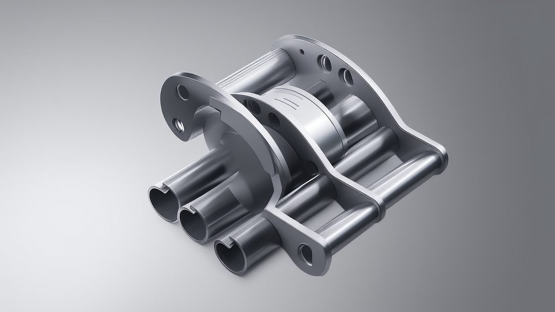
Energy Storage AI part image
A Sourcing Checklist for Energy Storage Components and Machined Baseplates
Send this to every shop on your shortlist. The answers sort them faster than any sales call.
- Can they state a flatness target on the cooling face (e.g. ±0.005 mm) - not just 'machined flat'?
- Do they verify finish with a profilometer and report Ra, not 'smooth'?
- Can they machine and plate copper bus bars and hold contact-face tolerance in writing?
- Do they run stress-relief so the part stays flat after thermal cycling, not just on day one?
- Will they provide material mill certs, FAI, and batch traceability on every lot?
- Are quality systems real - ISO 9001 at minimum, ISO 13485 or IATF 16949 discipline a plus?
- Can they scale from prototype to 500,000+ parts a month without re-qualifying the process?
- Do they answer engineering questions with numbers, not adjectives?
A supplier that clears all eight is rare and worth keeping. One that stumbles on flatness verification or traceability should not be on a pack where heat is a safety issue.
Common Mistakes Buyers Make with Battery Box Parts and CNC Power Parts
Most thermal failures were decided at the sourcing desk, not on the shop floor.
- Specifying 'machined flat' instead of a number on the cooling face - then wondering why the pack runs hot.
- Treating the baseplate as a structural part and forgetting it is the primary heat path.
- Choosing aluminum bus bars for high current to save weight, then paying it back in conductor heat.
- Skipping stress-relief, so the part is flat at incoming inspection but moves after thermal cycles.
- Leaving finish as 'smooth' on the drawing, with no Ra target to verify or reject against.
- Ignoring traceability - without batch records, one hot joint becomes a full pack investigation.
- Picking a supplier on price per kilogram rather than flatness, finish, and process control.
None of these are exotic failures. They are habits: vague specs, skipped verification, and price-led sourcing. The right supplier makes the careful habit the easy default, which is exactly what a thermal part deserves.
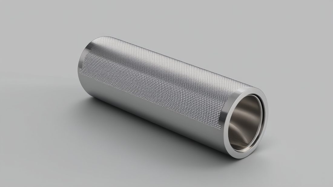
Energy Storage AI part image
Energy Storage AI part image
Energy Storage AI part image
Energy Storage AI part image
FAQ: thermal management & Energy Storage Buyer Questions
A: Heat shortens cell life steeply - a pack running 10-15 C hotter can lose a large share of its cycle life and face thermal-runaway risk. Thermal management keeps cells in the 25-35 C band where they deliver rated life, which directly protects warranty and replacement cost.
A: Hold the cooling contact face to about ±0.005 mm flatness and verify it with a CMM. A flat, smooth face (down to Ra 0.2 µm / 8K where the interface sits) lets the thermal interface material seat evenly so there are no hidden hot gaps.
A: Use copper where high current flows through tight runs - it conducts roughly twice the current of aluminum at equal size and stays cooler. Use aluminum for large, light, flat baseplates and structures. Most well-designed packs use both in different places.
A: CNC power parts such as bus bar contacts and terminal blocks set the contact resistance. Tight, flat, well-plated contacts keep resistance - and therefore I-squared-R heat - low. Loose or misaligned contacts create local hot spots the cooling system cannot fix.
A: Ask for a written flatness target on the cooling face, profilometer-verified Ra, stress-relief in the process, material mill certs, FAI, and batch traceability. Real quality systems (ISO 9001 minimum, ideally ISO 13485 or IATF 16949 discipline) and engineering answers with numbers are the signals that matter.
A: Yes. From our Dongguan plant we run both small custom orders and 500,000+ parts per month on 60+ CNC machines, so an energy storage program can move from first prototype to full production without re-qualifying the source - while keeping the same documented process and traceability.
Designing a cooled, reliable energy storage pack starts with the parts underneath the cells. Send us your drawing and we will return a free DFM review with flatness, finish, and material recommendations for your baseplates and bus bars - no obligation, just a clear engineering answer.
Request a Free CNC Quote