Turn-Mill Composite vs Re-Chucking: Motor Shaft Machining Cost (2026 Guide)
You can compare two motor shaft quotes line by line and still choose the wrong process. The unit price looks lower on the sheet that re-chucks the part three times, so it wins the spreadsheet — and then your assembly line sees shafts whose journals and mounting flats drift out of relationship, an intermittent whine in the reducer, and a supplier arguing that every dimension meets print. The cost did not disappear. It moved downstream, into your inspection, your scrap, and your warranty budget.
This guide is written for the engineers and buyers who have to decide how a drive shaft or transmission mating part will be machined before a purchase order goes out. We compare turn-mill composite machining with conventional CNC turning plus re-chucking on the things that actually decide cost: number of setups, how the datum chain is built, cumulative error, tolerance capability, inspection burden, and the hidden costs a low quote leaves out. We keep the discussion in cost drivers and ratios rather than invented prices, because the honest answer depends on your geometry, volume, and tolerance stack.
We are LusterControl, the brand of Dongguan Licun Technology Co., Ltd. Since 2015 we have spent fifteen years on CNC stainless-steel mirror turning: 60 CNC machines, a 4,000 m² plant after the 2026 expansion, and a general monthly output around 500,000 parts. Every number in this guide comes off our own floor. Read it as a shop-floor conversation about motor shaft machining, with the trade-offs left in and no claim that one process wins every program.
Table of Contents
- 1. What Motor Mating Parts and Transmission Structures Really Demand
- 2. Turn-Mill Composite Machining vs Re-Chucking: The Real Cost Drivers
- 3. Motor Shaft Machining: Where Cumulative Error Enters
- 4. Turn-Mill Composite: One Setup from Bar to Finished Shaft
- 5. Tight Tolerance CNC: Holding Coaxiality Across a Production Batch
- 6. CNC Precision Machining: Counting Setups, Scrap and Inspection Hours
- 7. Turn-Mill Composite vs Re-Chucking: A Decision Matrix for Your Program
- 8. Buyer's Checklist for Motor Shaft Machining Suppliers
- 9. Common Mistakes in Tight Tolerance CNC of Motor Mating Parts
- 10. Turn-Mill Composite Machining: The Hidden Costs a Low Quote Leaves Out
New Energy Vehicles (Three Electric) CNC precision component
What Motor Mating Parts and Transmission Structures Really Demand
Before you compare processes, be clear on what a drive shaft is actually being asked to do.
- Motor mating parts
- The machined interfaces on a drive or generator that locate and couple it to the next component — shaft journals, mounting pilots, end faces, keyways, and threaded or splined ends. Their job is to transmit torque and locate the part concentric to a rotation axis, not merely to hit a set of individual dimensions.
- Transmission structures
- The shafts, hubs, and coupling features in a reduction gearbox or e-axle that carry load between the motor and the wheel. They are judged on the relationship between features — coaxiality, perpendicularity, and face runout — as much as on any single size.
- Re-chucking
- Removing a partly machined part from one fixture and re-clamping it in another to add or finish features. Each re-chuck re-establishes the datum, and each re-establishment is a fresh source of positional error.
- Cumulative error
- The stack-up of small errors from each setup and operation. A part can pass every individual dimension check and still fail assembly because errors from separate clampings added up in the relationships between features.
A motor shaft rarely fails because one diameter is a few microns off. It fails because two features that should share an axis do not, because an end face is not square to the journal, or because a keyway position wandered relative to the pilot. Those are relationship problems, and relationship problems are created by the number of times the part is held. That is why the choice between one setup and three is not a clerical detail on a routing sheet — it is the single biggest process decision in motor shaft machining.
Three relationships that decide whether a shaft sits true
- Coaxiality between the bearing journals, the motor pilot, and the coupling end — this sets how evenly the shaft runs and how much load the bearings see.
- Perpendicularity of the mounting face and shoulder to the shaft axis — a face that is out of square tilts the assembly and loads the seal or coupling on one side.
- Position of keyways, flats, and cross-holes relative to the datum features — this decides whether the mating component slides on and locks where the design intends.
Why a part can pass inspection and still fail assembly
Conventional inspection often measures diameters and lengths one at a time, each against its own tolerance. A re-chucked part can satisfy every one of those numbers and still carry the errors of three clampings in the relationships between them. You only find out at assembly, when the coupling binds, the reducer whines, or the runout check fails. By then the parts are already paid for. If you are sourcing automotive CNC parts for a drivetrain program, ask which relationships the supplier measures — not just which dimensions.
New Energy Vehicles (Three Electric) CNC precision component
Turn-Mill Composite Machining vs Re-Chucking: The Real Cost Drivers
Two routes can make the same shaft. Here is where their costs actually diverge.
Turn-mill composite machining finishes turned and milled features in one clamping; the conventional route turns the shaft, moves it to a mill for flats, keyways, or ports, then re-fixtures it to finish the journals. The table below is the comparison we use with buyers who want to know why two quotes differ. Read it as a map of cost drivers, not a price list.
| Factor | Turn-mill composite | Turn then re-chuck |
|---|---|---|
| Setups for a journal + flat + keyway shaft | One clamping | Two or three fixtures |
| Source of coaxiality | Built in by the spindle axis | Re-established at every transfer |
| Mating-feature capability | ±0.005 mm held in process | Shop-dependent; often checked only at final |
| Cumulative error exposure | Minimal — one datum chain | Grows with each re-clamp |
| Inspection setups | Fewer relationships to measure | More CMM setups, more drift risk |
| Scrap exposure at transfer | No transfer between rough and finish | Damage and rework between fixtures |
| Cycle-time structure | Fewer handled operations, longer machine cycle | More handling, shorter individual cycles |
| Best fit | Coaxial, high-volume drivetrain shafts | Simple geometry or very low volume |
| Relative cost profile | Higher machine rate, lower downstream cost | Lower unit quote, higher hidden cost |
Six cost drivers, one at a time
- 1. Setup count. Every extra clamping is extra handling, extra setup time, and one more chance to clamp a finished surface too hard or off-square.
- 2. Datum chain. One setup means one datum; three setups mean three approximations of it. Each approximation spends inspection time to prove and carries risk if it drifts.
- 3. Scrap and rework. A part damaged between fixtures is usually discovered after more value has been added, so the loss is larger than the operation that caused it.
- 4. Inspection burden. Re-chucked parts need more measurements to prove relationships. That is real labour and real cycle time on your incoming side.
- 5. Lead time. Transfers and queue time between machines stretch a route even when each individual operation is quick.
- 6. Volume. At low quantity, setup costs dominate and a simple re-chucked route can be the rational choice; at volume, consistency and reduced inspection tend to favour one setup.
The cheaper quote is the one with fewer hidden operations. Count the clampings before you count the currency.
Motor Shaft Machining: Where Cumulative Error Enters
Follow the material through the route and you can see exactly where the risk is created.
To understand the cost difference, you have to understand the process. Here is the three-step route we use on shaft work, with the energy source, the medium, and the result at each stage — and what each stage means for the relationship between your features.
Step 1 — Rough from traceable bar
Energy source: machine power removing bulk stock from certified stainless or alloy bar. Medium: a rigid chuck holding the blank, with the heat lot carried with the job. Result: a near-net shape with stock deliberately left on the functional journals and faces. We take the heavy cuts early because removing a lot of material after finishing introduces stress and can move the very surfaces you just made true.
Step 2 — Turn the journals and pilots
Energy source: a controlled cutting edge at a stable speed and feed. Medium: the same clamping, with the part still located on its original datum. Result: diameters and faces that share one axis, because the spindle defined that axis. This is the stage that establishes the coaxiality the whole part depends on.
Step 3 — Add flats, keyways, and ports without moving the part
Energy source: live tooling in a turn-mill centre, driven perpendicular to the turning axis. Medium: the part still in its first clamping. Result: milled features cut in a known relationship to the turned axis, so a keyway lines up with the pilot and a cross-port lands where the drawing says — without re-gripping the shaft.
What re-chucking does to the same part
In the conventional route, step 3 happens in a different machine after the shaft is removed and re-clamped. The mill has to find the axis again, usually from a turned diameter or an end face. Any error in that find — a chip under the jaw, a slightly off indicator, a jaw that marks a finished surface — becomes an error in the keyway position. Repeat the transfer for another feature and the errors stack. That stack is cumulative error, and it is the reason a re-chucked part can look perfect and assemble badly.
New Energy Vehicles (Three Electric) CNC precision component
Turn-Mill Composite: One Setup from Bar to Finished Shaft
The value of one clamping is not speed. It is that the geometry stops depending on the operator.
Turn-mill composite machining is the most useful process decision on a coaxial drivetrain shaft. Instead of passing the part between a lathe and a mill, a single machine turns, mills, drills, and taps while the shaft stays in one fixture. The relationship between features is then a property of the machine's axes, not of how carefully somebody re-clamped the part at 2 a.m.
What one clamping actually protects
Concentricity of the journals to the pilot, perpendicularity of the shoulder to the axis, and the clocking of a keyway to a port. These are the features that decide whether torque transmits evenly and the shaft runs true. If the pilot is off-axis, the coupling loads one side; if the shoulder is out of square, the bearing sees a bending moment it was not designed for. Both can trace back to a re-clamp that looked fine.
Turn-mill composite vs a transferred route
| Feature | Turn-mill composite (one setup) | Transferred route (re-chucked) |
|---|---|---|
| Journal-to-pilot coaxiality | Held by a single spindle axis | Depends on re-locating a diameter |
| Keyway clocking to port | Set by live-tool position in one fixture | Set at a second setup on a mill |
| Shoulder face squareness | Finished in the turning setup | May be finished after re-clamp |
| Mating-feature capability | ±0.005 mm window held in process | Shop-dependent; final inspection only |
| Risk of marking a finished surface | Low — no re-grip of finished faces | Present at every re-clamp |
| Inspection report length | Shorter — fewer relationships to prove | Longer — more datum checks |
Tight Tolerance CNC: Holding Coaxiality Across a Production Batch
A tolerance is only real if it survives the whole batch and the whole shift.
Specifying ±0.005 mm is easy. Holding it through a production run is a process question. On a motor shaft the risk is rarely one bad part; it is a slow drift through a batch so the last hundred pieces sit at the edge of the window. We treat tolerance as an in-process control, not a final-inspection filter.
Tool life and heat are part of the tolerance
A fresh insert and one near end of life leave different surfaces at the same offset, so we set tool life against dimensional trend and finish rather than a fixed piece count. Stainless and alloy shafts hold heat at the cutting zone: a part measured hot is not the part measured at room temperature. We sequence roughing and finishing so functional features are cut when the part is stable and inspect at a controlled temperature.
Where ±0.005 mm is worth paying for
| Feature | Hold ±0.005 mm? | Reason |
|---|---|---|
| Bearing journals and motor pilot | Yes | Sets running axis and bearing load distribution |
| Shoulder face to axis | Yes, plus a geometric callout | Squareness, not just size, decides the load |
| Keyway width and position | Yes on position; width per standard fit | Width is a gauge job; position drives assembly |
| Thread ends | Per standard gauge | A thread gauge, not a CMM, is the right tool |
| Non-functional reliefs and chamfers | No — use a general tolerance | Tightening them adds cost, not performance |

New Energy Vehicles (Three Electric) CNC precision component
CNC Precision Machining: Counting Setups, Scrap and Inspection Hours
Cost is not a single number on a quote. It is a handful of activities you can count.
We are often asked for a price comparison between the two routes. We give cost drivers and ratios, not a universal figure, because the honest answer depends on your shaft, your alloy, your tolerance stack, and your monthly volume. A supplier who quotes a fixed saving before reading the drawing is guessing. Here is how to compare two quotes on equal terms.
The cost items that actually move
| Cost item | Turn-mill composite | Re-chucked route |
|---|---|---|
| Machine time per part | One longer, consolidated cycle | Several shorter cycles |
| Handling and setup labour | Low — one load and unload | Higher at each transfer |
| Work-in-process between machines | Minimal | Queues between lathe and mill |
| Scrap from transferred parts | Lower exposure | Higher — damage after value is added |
| Inspection labour | Fewer relationships to prove | More CMM setups and datum checks |
| Lead time | Shorter route | Longer — transfers add queue time |
| Flexibility at very low volume | Less economical | Often the rational choice |
Why we will not quote a universal saving
A simple shaft with loose tolerances made in tens of pieces does not need a turn-mill centre, and anyone who tells you otherwise is selling machine time. A coaxial drivetrain shaft with tight relationships made in thousands is a different calculation: fewer setups, less inspection, and less scrap usually outweigh the higher machine rate. The right comparison is total cost per accepted part at your volume, not the number in the unit-price column.
Turn-Mill Composite vs Re-Chucking: A Decision Matrix for Your Program
A decision table beats a parameter dump when you need to choose this week.
Use the table below as a starting point, then pressure-test it against your own geometry, tolerance stack, and volume. If you want a second opinion from a shop that runs both routes, send us your drawing for a free DFM review — you will get a short, specific answer on which features drive cost.
| Your requirement | Recommended route | Why it wins |
|---|---|---|
| Coaxial journals, pilot and coupling end with tight relationships | Turn-mill composite in one setup | Relationships built by one axis, not re-clamped |
| High-volume e-axle or reducer shaft program | Turn-mill composite, in-process gauging | Consistency and lower inspection burden at volume |
| Simple shaft, loose tolerances, tens of pieces | CNC turning with a careful single re-chuck | Setup cost dominates; one setup is enough |
| Design still changing, geometry not frozen | Conventional route for prototypes | Avoid committing to dedicated tooling too early |
| Drawing with a tight tolerance on every feature | Either — fix the drawing first | Identify functional surfaces before choosing a process |
| Audit-driven supply chain needing batch records | Either, with tight tolerance CNC and traceability | Evidence and consistency matter more than the first article |
Pros
- Choose turn-mill composite if your part needs coaxiality, squareness, or clocking between turned and milled features.
- Choose turn-mill composite if your volume is high enough that fewer setups and less inspection outweigh the machine rate.
- Choose the re-chucked route if the geometry is simple, the tolerances are general, and the quantity is small.
- Choose the re-chucked route for prototypes while the design is still moving and dedicated setup is not justified.
Cons
- Do not pay for one setup if your drawing does not need the relationship it protects — spend the money on the functional features instead.
- Do not assume a re-chucked part is out of tolerance; ask which relationships the supplier measures before judging it.
- Do not decide on unit price alone; count clampings, inspection, and scrap exposure first.
New Energy Vehicles (Three Electric) CNC precision component
Buyer's Checklist for Motor Shaft Machining Suppliers
The things to put in writing before a purchase order, not after a problem.
Supplier selection is less about adjectives and more about what a factory will put in writing. Whatever route you choose, these are the items we would request in your position — and the ones we keep ready because our customers ask for them.
- A DFM response that names your functional surfaces and states which relationships the chosen route builds in and which it has to inspect. A supplier who says yes to every callout without comment has not read the drawing.
- A route sheet showing the number of setups, with the datum identified for each one.
- A material certificate and heat-lot identification tied to the specific batch you receive — EN 10204 3.1 where documented identity is required.
- An initial dimensional report that measures relationships (coaxiality, perpendicularity, keyway position), not just individual diameters.
- A capacity and ramp statement: monthly output, the machines behind it, and how your volume fits into the plan.
Red flags in a re-chucking quote
- The quote is instant and unconditional, with no question about the tolerance stack, the functional features, or how many setups the route needs.
- The supplier measures diameters but cannot show how it verifies coaxiality or keyway position after re-clamping.
- Traceability is available but not included in the batch documentation.
- The sample is beautiful and the production control plan is vague. One good shaft is not a process.
- The address is an office and a visit to the machining floor is politely avoided.
If you want to see how we handle the first item, look at how our technical guides on drivetrain and CNC machining break down setups and tolerances, then send us your drawing. A DFM review is useful information whether or not you place an order.
Common Mistakes in Tight Tolerance CNC of Motor Mating Parts
Most drivetrain shaft failures are process failures already visible at the drawing stage.
| Mistake | Symptom you will see | What we do instead |
|---|---|---|
| Finishing journals before all heavy cuts | Passes inspection, drifts after assembly | Rough first, then finish functional surfaces in a stable state |
| Re-clamping between journal and keyway | Keyway clocking varies, coupling binds | Turn-mill composite in one setup with a common datum |
| Tight tolerance on every feature | High cost, no functional gain | Tighten only surfaces the assembly depends on |
| Inspecting diameters, not relationships | Print passes, assembly fails | Measure coaxiality and squareness on the same datum |
| Treating deburr as a manual afterthought | Burrs at keyways and ports, intermittent fit issues | Defined deburr operation with a sample borescope check |
Mistake 1: choosing the cheapest setup count
A re-chucked route wins the unit-price column and loses on relationships. Before accepting the lower quote, ask how many times the part leaves a fixture and which features are re-established each time. If the answers are vague, the saving is not real — it is deferred into your inspection and scrap.
Mistake 2: treating the sample as the process
Any supplier can make one excellent shaft on a quiet afternoon. The question is what the five-hundredth looks like at the end of a shift. Ask for the control plan: how offsets are checked, when tools are changed, and what happens when a dimension starts to walk. If there is no answer, the sample was luck.
Mistake 3: finishing before the stress is out
Heavy cuts after a fine finish move the surface you just made true. We rough first, leave stock on functional features, and finish in a stable condition. After machining, stainless components need cleaning and passivation that restores corrosion resistance without attacking the finish; ASTM A967 is the standard reference we use as the framework for that treatment and the acceptance discussion with the buyer.
New Energy Vehicles (Three Electric) CNC precision component
Turn-Mill Composite Machining: The Hidden Costs a Low Quote Leaves Out
The most expensive part of a cheap shaft is what happens after it arrives.
Buyers who compare only unit price tend to rediscover the same costs in a different department. A re-chucked shaft can be cheaper to make and more expensive to own. Here is the hidden-cost map we walk through with drivetrain teams, adapted from the way experienced sourcing teams account for a machining decision.
| Hidden cost | Where it shows up | How a one-setup route reduces it |
|---|---|---|
| Extra incoming inspection | Your QC bench, every batch | Fewer datum relationships to prove |
| Scrap after added value | Late in the route, when the part is worth more | No transfer between rough and finish |
| Assembly rework | Fit issues and line stoppages | Clocking and coaxiality built in |
| Warranty exposure | Field returns and quiet claims | More consistent relationships across the batch |
| Lead-time buffer | Safety stock and expedited freight | Shorter route, less queue between machines |
| Engineering time | Debates about whose tolerance is wrong | A clear datum chain to point to |
How to compare two quotes honestly
- 1. Ask both suppliers to state the number of setups and mark where the part is re-clamped.
- 2. Ask which relationships each route measures, and on which datum, not just which diameters.
- 3. Put the inspection labour for each route into the comparison, even if it happens in your own plant.
- 4. Ask what the scrap rate was on the last similar batch, and at what point in the route the scrap occurred.
- 5. Compare total cost per accepted part at your monthly volume, not the headline unit price.
We do not claim turn-mill composite is always the answer. For a simple shaft in small quantities, the conventional route is often the smarter buy. What we do claim is that the decision should be made with the whole cost map visible. If you want to see yours laid out for a specific part, send us your drawing for a free DFM review and tell us your target volume — we will show you which features pay for one setup and which do not.
Buy the route that makes the relationship repeatable. The relationship is what your assembly actually feels.
New Energy Vehicles (Three Electric) CNC precision component
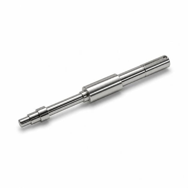
New Energy Vehicles (Three Electric) CNC precision component
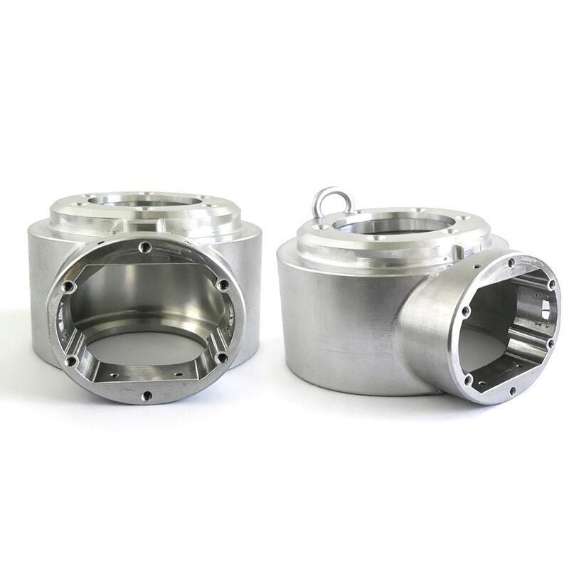
New Energy Vehicles (Three Electric) CNC precision component
FAQ: motor mating parts and transmission structures & New Energy Vehicles (Three Electric) Buyer Questions
A: No. For a simple shaft with general tolerances made in small quantities, setup cost dominates and a conventional single re-chuck is often the rational choice. Turn-mill composite tends to win when features must be coaxial or clocked to each other and the volume is high enough that fewer setups and less inspection outweigh the higher machine rate. Compare total cost per accepted part at your volume, not the unit-price column.
A: Every time a part leaves a fixture and is re-clamped, the supplier has to re-establish the datum from a diameter or face. Any small locating error becomes an error in the new features, and errors from separate setups stack. A shaft can then pass each individual dimension check and still fail on coaxiality, squareness, or keyway position at assembly. One setup removes most of that stack.
A: Spend it on functional relationships: bearing journals, the motor pilot, shoulder faces square to the axis, and keyway position. Use a standard gauge for threads and a general tolerance on non-functional reliefs and chamfers. A drawing that tightens everything is expensive without being more functional — identify the surfaces your assembly depends on first.
A: Ask for the number of setups, which features are re-established at each re-chuck, which relationships are measured (coaxiality, perpendicularity, keyway position) and on which datum, the material certificate and heat-lot traceability, and the scrap rate on the last similar batch. Put the inspection labour for each route into the comparison. A supplier who answers these questions has read the drawing.
A: We use ASTM A967 as the reference framework for chemical passivation of stainless steel and can supply EN 10204 3.1 material certificates with the batch when required. LusterControl is ISO 9001 certified under certificate 25025Q13824R0S, valid through 2028-12-02. Our ISO 13485 quality system is established with certification in progress, and IATF 16949 is at the application stage. We state each status precisely.
A: Yes. Confidentiality is our normal operating procedure. We run NDA and controlled drawing access for programs including De'Longhi, Donlim, and Breville, and apply the same discipline to anonymous EV drivetrain projects. We discuss process and capability, never a customer's identity or design details.
Send us your motor shaft or transmission mating-part drawing for a free DFM review. Tell us your target monthly volume, the functional relationships that must hold, and the tolerances you actually need — and we will show you whether one setup or a conventional route is the lower-cost choice for your part, with the cost drivers laid out honestly before you commit a purchase order.
Request a Free CNC Quote