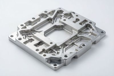
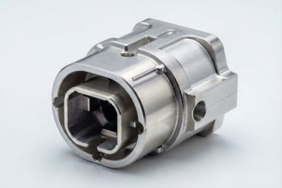
Ultra-Clean CNC Machining for Semiconductor Vacuum Chambers
When a single 300 mm wafer carries thousands of dollars of patterned circuitry, the last thing you can afford is a stray machining burr or a fingerprint of cutting oil inside the chamber that later deposits onto the substrate. In semiconductor manufacturing, contamination is not a cosmetic nuisance - it is yield, and yield is money. That is why the teams building deposition, etch, and metrology chambers treat the inside of every vacuum chamber as a cleanroom in miniature, and why we have spent years building ultra-clean machining discipline into how we cut, finish, and package vacuum chamber parts.
This guide walks through what ultra-clean machining actually requires for semiconductor vacuum chambers, how high flatness machining keeps a flange sealing under hard vacuum, why the right CNC machining center changes your leak-rate odds, and where PEEK machined parts replace metal inside the vessel. We write it the way we would brief a process engineer on the floor: concrete, with numbers, and honest about the mistakes that cost the most.
LusterControl (Dongguan Licun Technology Co., Ltd.) has run precision CNC work since 2015 from a 2,000 m2 Dongguan source factory with 60+ CNC machines and monthly output around 500k parts. We hold ISO 9001, have completed ISO 13485, and are pursuing IATF 16949 - the same documented, traceable discipline that semiconductor and medical programs expect. The numbers and trade-offs below are the ones we argue about with customers before a single chip is cut.
Table of Contents
- 1. Why Semiconductor Components Demand a Clean-Room Mindset
- 2. What Ultra-Clean Machining Means for Vacuum Chambers
- 3. Designing Vacuum Chamber Parts for a Stable Vacuum
- 4. How High Flatness Machining Protects the Vacuum Seal
- 5. Selecting a CNC Machining Center for Chamber Production
- 6. Where PEEK Machined Parts Outperform Metal in Chambers
- 7. Surface Finish and Materials for Semiconductor Components
- 8. Common Pitfalls in Vacuum Chamber Parts (and How to Avoid Them)
Semiconductor: circuit,board
Why Semiconductor Components Demand a Clean-Room Mindset
One particle on a wafer can scrap a die worth more than the chamber that made it.
A modern logic wafer may hold hundreds of chips, each worth real money once packaged. A single particle of steel, a sliver of swarf left from machining, or a film of coolant residue inside the chamber can migrate onto the substrate during a pump-down or a process step, becoming a defect site. In high-volume fabs the cost of a contaminated lot is not just the wafers - it is the tool downtime, the engineering investigation, and the lost queue position.
What a particle actually costs you
- Yield loss - one killer particle on a critical layer can fail an entire die.
- Tool downtime - decontaminating a chamber stops every lot behind it in the queue.
- Engineering hours - root-causing a contamination event is slow, manual, and expensive.
- Customer confidence - repeat events put your process qualification at risk.
| Contamination source | How it enters the chamber | Control we apply |
|---|---|---|
| Machining burrs and swarf | Left in blind holes or threads | Deburr, ultrasonic clean, visual plus zoom inspection |
| Cutting fluid residue | Trapped in pores, outgasses under vacuum | Low-residue coolant, solvent wash, bake-out |
| Metallic particles | Tool wear, handling | Sealed handling, ionized-air blow-off, HEPA environment |
| Skin oils and fibers | Manual handling | Gloves, non-shedding wipes, gowned handling |
The mindset matters more than any single step. A shop that treats cleanliness as a final wash will never be as reliable as one that designs it into the cut, the handling, and the packaging. For semiconductor components, clean is a process property, not a finishing touch.
Semiconductor: microchip
What Ultra-Clean Machining Means for Vacuum Chambers
Clean machining is about what you remove after the cut as much as how you cut.
Ultra-clean machining is the discipline of producing a part that enters the vacuum chamber with no burrs, no loose particles, no cutting-fluid film, and no reactive residue. On a chamber that will see pressures far below atmospheric, even a microscopic film can outgas for hours, raising the base pressure and contaminating the process. The goal is a part whose surface is inert, bare, and physically free of anything that can move.
The four contamination vectors we control
- Burrs
- Raised edges from cutting that break off and become loose particles.
- Swarf
- Fine chips trapped in holes, slots, or threads during machining.
- Coolant film
- Residual oil or emulsion that outgasses and leaves a contaminate layer.
- Handling debris
- Skin oils, fibers, and dust picked up between machines.
Why oil and coolant choice decides your base pressure
Standard soluble coolants leave a tenacious film that survives a rinse and only reveals itself as outgassing during pump-down. We use low-residue, easily removed coolants and, for the most critical vacuum chamber parts, minimize coolant contact through dry or minimal-quantity lubrication where the geometry allows. After machining, the part goes through an ultrasonic clean, a solvent or aqueous wash, and where the spec calls for it, a controlled bake-out to drive off absorbed volatiles.
- Machine with sharp tooling and minimal-residue coolant to limit burr formation.
- Deburr every edge; pay special attention to cross-holes and threaded features.
- Ultrasonic clean, then aqueous or solvent wash to strip coolant film.
- Bake-out where the process demands it, to release absorbed volatiles.
- Inspect, bag, and seal in a controlled environment before shipping.
Notice that none of these steps is heroic on its own. The discipline is doing all of them, every time, and proving it with inspection records.
Designing Vacuum Chamber Parts for a Stable Vacuum
A chamber that leaks is a chamber that never reaches base pressure.
Before we cut a single feature, the design decides whether a vacuum chamber part will hold vacuum. Wall thickness, flange geometry, seal groove location, and bolt-circle layout all set the leak-tightness and the repeatability of the seal. We review these with customers early, because a design that fights the physics is expensive to machine into compliance.
Flange and seal geometry that actually seals
- Use a proven flange standard (CF, KF, or ISO-F) rather than a custom face.
- Keep the seal groove concentric and dimensioned to the gasket, not 'about right'.
- Size the bolt circle so clamp load is even and the flange stays flat under torque.
- Avoid blind pockets near the seal that trap gas and slow pump-down.
| Seal type | Pressure range | Reusability | Machining note |
|---|---|---|---|
| CF (ConFlat) | Ultra-high vacuum, below 1e-8 mbar | Usually single-use | Requires a precision knife edge; flatness critical |
| KF (Klein Flange) | Rough to high vacuum | Reusable | Quick clamp, lower flatness demand |
| ISO-F (large) | High vacuum | Reusable | O-ring groove, concentricity key |
For most deposition and etch chambers the CF-style knife-edge flange is the workhorse because it seats metal-to-metal and survives repeated bakes. The catch is that the knife edge and the mating face demand the flatness and finish we cover next.
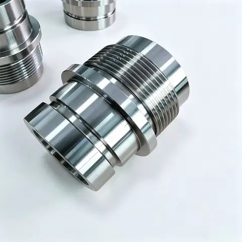
Semiconductor: factory
How High Flatness Machining Protects the Vacuum Seal
A seal does not care about your average tolerance - it cares about the gap at the worst point.
High flatness machining is what lets a flange seat against its mate with no path for gas to creep through. Vacuum sealing is unforgiving: a thousandths-of-a-millimeter waviness across a 200 mm flange is enough to leave a microscopic channel that leaks forever. Flatness, not just diameter tolerance, is the property that decides leak-tightness.
Flatness you should expect by flange size
| Flange diameter | Typical flatness target | Why it matters |
|---|---|---|
| Up to 100 mm | plus/minus 0.005 to 0.01 mm | Small CF faces; tight knife-edge seat |
| 100 to 250 mm | plus/minus 0.01 mm | Most chamber ports and viewports |
| Over 250 mm | plus/minus 0.02 mm, mapped | Large doors; measure full face, not edge |
We hold positional accuracy to plus/minus 0.005 mm and can take sealing faces to a mirror-ready Ra 0.2 um when the process demands it. But flatness is also about how you measure: a large door flange should be mapped across the whole face, not just checked at the edge, or a low spot in the middle will hide until first pump-down.
Pros
- Reliable leak-tight sealing
- Repeatable across batches
- Survives repeated bakes
- Lower field failure rate
Cons
- Holding flatness costs more machine time
- Needs CMM or optical verification
- Large parts need fixturing skill
That is the payoff of high flatness machining: the part passes the test the first time, because the second time costs you a launch date.
Selecting a CNC Machining Center for Chamber Production
Five axes or three is not a status question - it is a tolerance question.
A vacuum chamber is rarely a simple plate. It has ports on multiple faces, internal bores, a knife-edge flange, and features that must stay mutually true. The CNC machining center you choose decides how many setups it takes and how much datum shift creeps in with each re-clamp.
Capability comparison
| Process | Best for | Typical accuracy | Setup risk |
|---|---|---|---|
| 3-axis milling | Plates, simple flanges | plus/minus 0.01 mm | High, re-clamp drift |
| Turn-mill | Cylindrical bodies, bores | plus/minus 0.008 mm | Low, one clamp |
| 5-axis | Multi-face ports, complex chambers | plus/minus 0.005 mm | Lowest, single setup |
For a chamber body with ports on three faces, 5-axis machining in a single setup keeps every feature on one datum and holds plus/minus 0.005 mm across all of them. Re-fixturing a 3-axis run two or three times introduces 0.02 to 0.05 mm of datum shift per clamp - exactly the kind of error that ruins a knife-edge seat.
- Confirm 5-axis single-setup capability, not 3-axis with re-fixturing.
- Ask how flatness is verified - CMM map versus edge check.
- Require material certs traceable to the heat lot.
- Get a first-article report, not just a photo of a finished part.
The right CNC machining center is the one whose accuracy envelope comfortably contains your tightest callout - with margin, not luck.
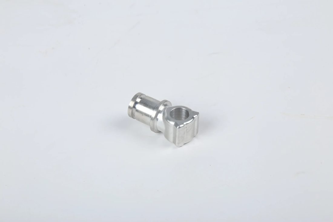
Semiconductor: metal
Where PEEK Machined Parts Outperform Metal in Chambers
Sometimes the best chamber material is not metal at all.
PEEK machined parts - components cut from polyetheretherketone, a high-performance thermoplastic - earn their place inside vacuum chambers where metal would be a liability. PEEK has very low outgassing, excellent chemical resistance, and no galvanic or particle-shedding risk, which makes it ideal for insulating fixtures, wafer-handling clips, and non-contact spacers deep inside the vessel.
PEEK versus metal for chamber internals
| Property | PEEK | Aluminum | Stainless 316L |
|---|---|---|---|
| Outgassing under vacuum | Very low | Low to moderate | Low |
| Particle shedding | None | Possible, oxide | Possible, wear |
| Chemical resistance | Excellent | Moderate | Good |
| Machinable tolerance | plus/minus 0.02 mm typical | plus/minus 0.005 mm | plus/minus 0.005 mm |
| Weight | Low | Low | High |
Pros
- Minimal outgassing protects base pressure
- No corrosion, no galvanic issues
- Light and easy to insulate
- Non-contaminating for wafer contact
Cons
- Lower stiffness than metal at temperature
- Tighter tolerance costs more than metal
- Not for high-load structural seats
- Needs sharp tooling to avoid melt
We machine PEEK to tight tolerances on dedicated setups, with sharp tooling and controlled feeds so the edge stays clean rather than melted. For wafer-handling and insulating roles inside the chamber, PEEK machined parts are often the safest choice you can make.
Surface Finish and Materials for Semiconductor Components
Finish is a function, not a shine - pick it by where the surface lives.
Inside a vacuum chamber, every surface has a job. A sealing face must be flat and smooth to seat. A gas-flow path should be clean to avoid trapping residue. A wafer-contact part should be inert and non-shedding. The right surface finish follows the function, and so does the material choice.
Finish choices by surface role
| Surface role | Target Ra | Treatment |
|---|---|---|
| Knife-edge or seal face | Ra 0.2 to 0.4 um | Precision machine, optional mirror |
| Gas-flow path | Ra 0.4 to 0.8 um | Clean machine, passivate |
| Structural wall | Ra 0.8 to 1.6 um | As-machined acceptable |
| Wafer-contact (PEEK) | Ra 0.8 um | Sharp-tooled, debris-free |
For stainless sealing faces we passivate per ASTM A967 to rebuild the chromium-oxide layer that makes the surface inert and corrosion-resistant - important because a corroding face releases particles into the vacuum. Our mirror line reaches Ra 0.2 um, the same 8K finish we use on medical and fluid parts.
Specify the Ra number and the post-treatment on the drawing. 'Smooth' is not a tolerance; 'Ra 0.4 um max, passivated per ASTM A967' is something a supplier can measure and prove.
Semiconductor: cleanroom
Common Pitfalls in Vacuum Chamber Parts (and How to Avoid Them)
Every failure below was decided at the drawing or sourcing stage.
- Leaving finish as 'clean' - unmeasurable, so it becomes whatever the shop feels like.
- Skipping flatness mapping on large flanges - a center low spot hides until pump-down.
- Choosing the wrong flange for the base pressure - a KF face asked to hold UHV.
- Ignoring outgassing from coolant film - looks clean, fails the vacuum test.
- Using metal clips where PEEK would avoid particle shedding.
- No traceability - one leak event becomes an untraceable mystery.
- State the target base pressure and bake temperature up front.
- Specify flange type and the flatness target for the full face.
- Call out Ra on every critical surface, plus passivation per ASTM A967 where used.
- Define cleanliness end-state: residual extractable, outgassing, or bake-out.
- Require material certs traceable to the heat lot.
- Ask for CMM first-article and batch traceability with every shipment.
None of these are exotic. They are the habits that separate a chamber that qualifies on the first try from one that burns a week of rework - and the right supplier makes the safe habit the default.
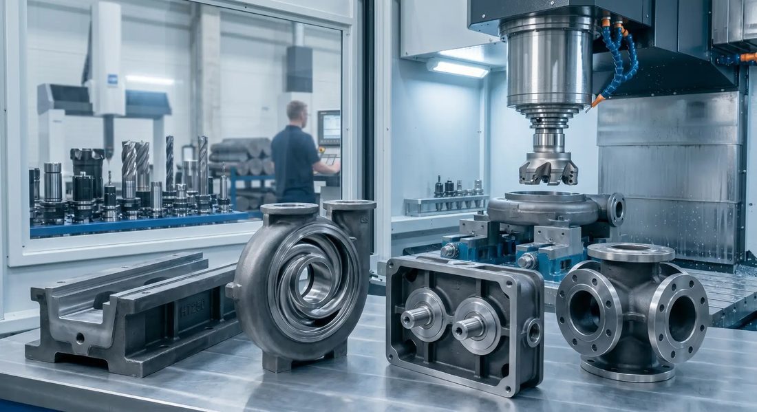
Semiconductor: lab
Semiconductor: robotic,arm
Semiconductor: welding
Semiconductor: warehouse
FAQ: semiconductor components & Semiconductor Buyer Questions
A: For a CF-style knife-edge or metal-seal face, target Ra 0.2 to 0.4 um, machined precisely and verified with a profilometer. Gas-flow and structural surfaces can run rougher (Ra 0.4 to 1.6 um) because they do not carry the seal. Always write the Ra number on the drawing rather than 'smooth'.
A: Flatness depends on flange size: roughly plus/minus 0.005 to 0.01 mm for faces under 100 mm, plus/minus 0.01 mm up to 250 mm, and plus/minus 0.02 mm mapped across faces larger than 250 mm. Large doors should be measured across the full face, not just at the edge, or a central low spot will leak on first pump-down.
A: Yes, and often they are the best choice for insulating fixtures, wafer-handling clips, and non-structural spacers because PEEK has very low outgassing, no corrosion, and sheds no metallic particles. It is not for high-load structural seats, and its tightest practical tolerance is around plus/minus 0.02 mm, looser than metal.
A: It means the part leaves with no burrs, no trapped swarf, no cutting-fluid film, and no handling debris - verified, not assumed. The workflow is low-residue machining, deburr, ultrasonic and solvent clean, optional bake-out, then inspection and sealed packaging in a controlled environment.
A: We verify flatness and finish with CMM mapping and profilometry, confirm material via heat-lot certs, and supply first-article inspection plus batch traceability. Final leak verification is typically a helium leak test performed by the customer or integrator against the spec we helped define.
A: Yes. We run first-article inspection on new designs, support low-volume custom chambers and fixtures, and scale to monthly volume across 60+ CNC machines while keeping the same documented process, cleanliness controls, and traceability.
Designing a vacuum chamber or its internals and want it to qualify on the first try? Send us your drawing and we will return a free DFM review covering flange choice, flatness targets, material (including PEEK machined parts), and cleanliness requirements - clear engineering, no sales pressure.
Request a Free CNC Quote