Why Optical Instruments Need Thermally Stable Machined Bases
Ask any optics engineer what ruins a measurement and they will not say 'the lens.' They will say 'the base moved.' A precision instrument is only as stable as the machined structure it is built on: the base sets the datum, the barrels hang the optics on that datum, and the adjustment seats let you trim the axis to perfection. If the base drifts a micron with the room temperature, every optical component mounted to it drifts with it.
This is an industry insight, written the way an engineer would explain it to a program manager. We walk through why optical components fail when the base drifts, what sub-micron stability actually buys an instrument, where Invar machining earns its place, how lens barrel machining defines the optical axis, what CNC instrumentation verification looks like, and how a precision base with real adjustment seats is designed. Every shop number here is a real process number from our floor.
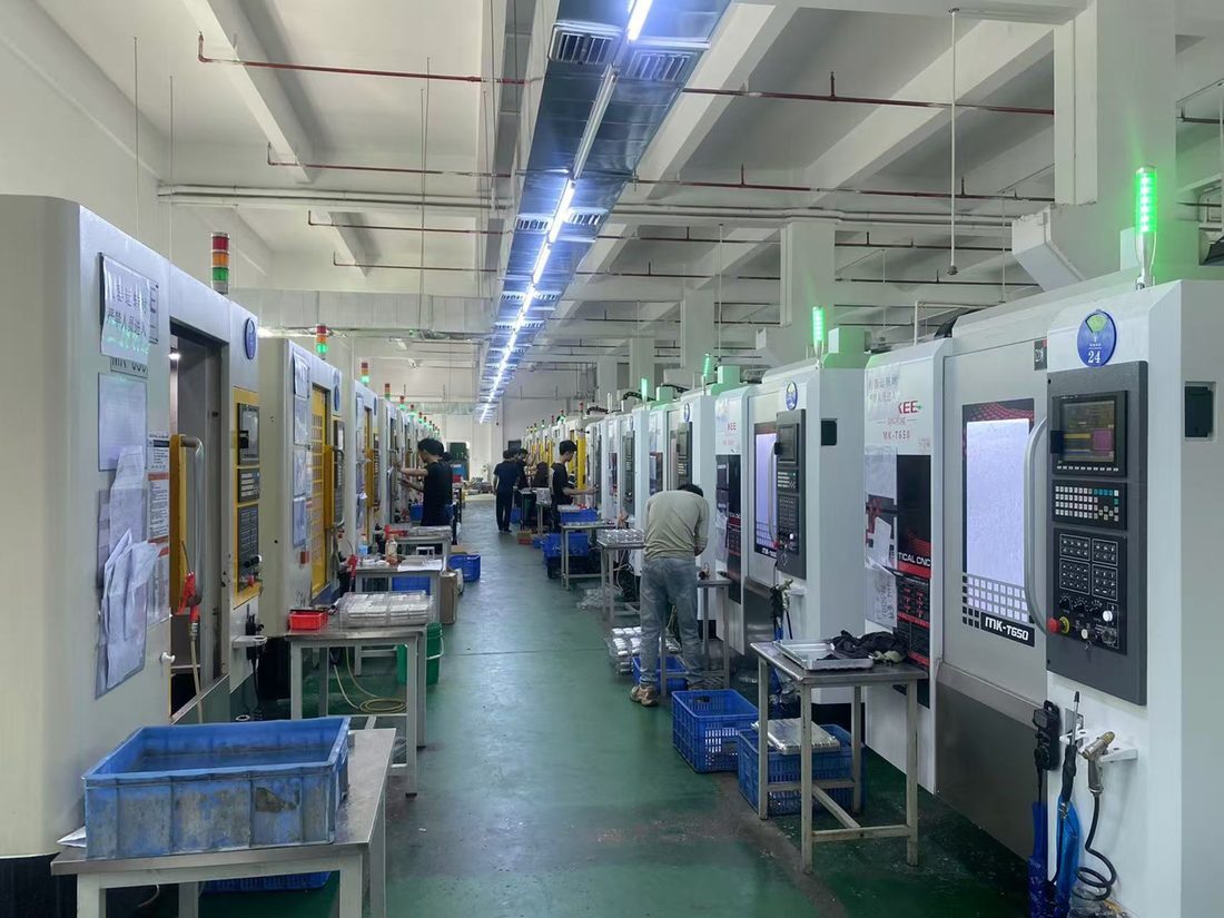
We are Dongguan Licun Technology Co., Ltd., brand LusterControl - a Dongguan source factory focused on stainless steel mirror machining since 2015, now 15 years in. We run 60+ CNC machines on a 2,000 m2 floor at roughly 500,000 parts a month, holding ISO 9001, with ISO 13485 completed and IATF 16949 in application. We serve the optical and instrumentation supply chain alongside medical, automotive, and UAV programs, and we have shipped precision parts to brands such as De'Longhi, Donlim, and Breville.
Table of Contents
- 1. Why Optical Components Fail When the Base Drifts
- 2. Sub-Micron Stability: The Number Instruments Are Judged On
- 3. Invar Machining for Bases That Refuse to Move
- 4. Lens Barrel Machining and the Axis It Defines
- 5. CNC Instrumentation: Measuring What the Optic Sees
- 6. Precision Base Design for Adjustment Seats
- 7. A Sourcing Checklist for Optical Components and Stable Bases
- 8. Common Mistakes in Sub-Micron Stability Programs
Optical CNC precision component
Why Optical Components Fail When the Base Drifts
The base is the datum everything else inherits - get it wrong and nothing downstream is true.
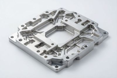
An optical instrument is a chain of datums. The base defines the primary reference plane; the barrels and mirror mounts reference that plane; the lenses and mirrors sit in the barrels. If the base warps under its own weight, expands with temperature, or distorts when bolted down, every optical component mounted to it inherits that error. The lens may be perfect and the measurement still wrong, because the foundation moved.
What a drifting base costs you
- Boresight walk - the optical axis tilts as the structure warms.
- Focus shift - the focal plane moves off the sensor or reticle.
- Repeatability loss - the instrument reads differently each time.
- Calibration churn - you recalibrate to cover a mechanical drift.
So the base is not a 'chunk of metal' - it is the first and most important optical component in the instrument. Treat it that way.
Optical CNC precision component
Sub-Micron Stability: The Number Instruments Are Judged On
Stability is not one number - it is what the structure does as the room warms a degree.
Sub-micron stability means the optical axis stays put as temperature, load, and handling change. The biggest enemy is thermal expansion mismatch: if the base, the barrel, and the mount expand at different rates, the axis walks every time the temperature moves. The second enemy is residual stress, which relaxes after machining and shifts the geometry. Both are designed out, not inspected out.
How we design for stability
- Match coefficients of thermal expansion across the assembly where possible.
- Use a low-CTE material (such as Invar) for the most stability-critical bases.
- Stress-relieve or anneal before the finish pass so the part does not move later.
- Symmetric, ribbed sections so expansion stays radial, not tilted.
- Single-datum machining so features stay mutually true.
| Material | CTE (ppm/K) | Note |
|---|---|---|
| Aluminum 6061 | ~23 | Light, needs compensation |
| Stainless 304 | ~17 | Corrosion-resistant, moderate |
| Invar 36 | ~1.2 | Near-zero drift, harder to machine |
Invar Machining for Bases That Refuse to Move
Invar is the material that refuses to move with temperature.
Invar (a 64Fe-36Ni alloy) has a coefficient of thermal expansion around 1.2 ppm/K - roughly one-twentieth of aluminum - so a base made from it barely moves as the lab warms a degree. That makes Invar machining the route to thermally stable optical bases for metrology and aerospace instruments. The catch is machinability: Invar is gummy and work-hardens like an austenitic stainless, so it needs rigid setups, sharp tools, and patient feeds.
Our Invar machining recipe
- Rigid, well-damped setup to stop chatter in a gummy alloy.
- Sharp carbide inserts and moderate speeds to avoid work-hardening.
- Through-tool coolant so heat leaves with the chip.
- Stress-relief bake before the finish pass to lock the size.
- CMM the critical planes at temperature-controlled conditions.
Pros
- Near-zero thermal drift
- Dimensionally stable over time
- Excellent for metrology bases
- Holds fine features once cut
Cons
- Gummy, work-hardens, slow to cut
- More expensive blank
- Needs rigid, damped setups
- Finishing demands patience
Optical CNC precision component
Lens Barrel Machining and the Axis It Defines
The optical axis is a line through concentric bores - break the chain and the image moves.
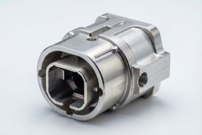
Lens barrel machining is the discipline of keeping every bore, seat, and thread on one common axis. The barrel is a stack of features - a front retaining thread, an intermediate lens seat, a rear seat, and a mounting flange - and if any one drifts off the common axis, the lenses no longer share an axis and the optical performance degrades. The work is all about a single, stable datum, referenced back to the base.
What we control on a barrel
- Turn the bore and outer diameter on one datum so they are concentric.
- Machine each lens seat square to the bore within a few microns.
- Cut the retaining threads coaxial and to a clean major diameter.
- Hold the mounting flange perpendicular so the barrel seats true to the base.
- Verify concentricity and seat perpendicularity on a CMM before release.
| Feature | Typical tolerance | Why it matters |
|---|---|---|
| Bore roundness | 0.002-0.003 mm | Lens seats without rocking |
| Seat perpendicular to bore | 0.005 mm | No tilt of the wavefront |
| Bore concentricity | 0.003 mm | Common optical axis |
| Thread major dia | +/-0.01 mm | Retainer seats without skew |
CNC Instrumentation: Measuring What the Optic Sees
You cannot hold sub-micron if you only measure after the part is off the machine.
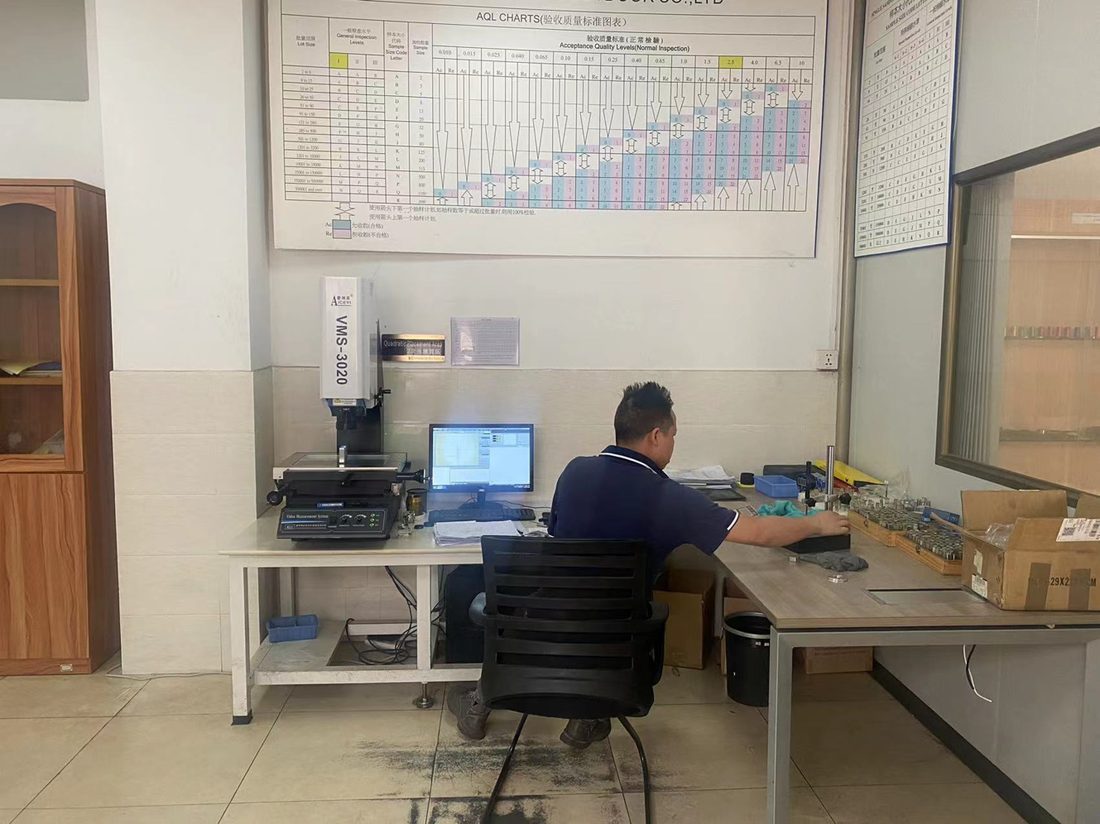
CNC instrumentation work means the measurement is part of the process, not an afterthought. In-process probing catches drift before the part is finished; a temperature-controlled CMM with an air-bearing spindle verifies concentricity and perpendicularity to sub-micron resolution. For optical structures we verify the optical-axis features - not just the easy diameters - because that is what the system cares about.
What to verify, and how
- Probe bore and seat in-process to catch thermal drift early.
- CMM concentricity and perpendicularity at controlled temperature.
- Air-gauge or air-bearing check for roundness where needed.
- First-article full report, then lot-level audit per batch.
- Document every number so the instrument can be traced to its part.
| Capability | What it gives you | Our floor |
|---|---|---|
| In-process probing | Catch drift before scrap | Standard on precision cells |
| Temp-controlled CMM | Sub-micron verification | Full datum report per FAI |
| Material certs | Known melt, traceable | Every lot |
| Lot traceability | Part back to raw bar | CoC per lot |
Optical CNC precision component
Precision Base Design for Adjustment Seats
The base is where you both lock the datum and leave room to trim it.
A precision base does two jobs at once: it establishes the primary datum, and it carries the adjustment seats that let you fine-tune the optical axis during assembly. Adjustment seats are the small, often overlooked features - kinematic mounts, screw-jack points, or flexure seats - that let a technician nudge a mirror or barrel into perfect alignment. Get the base right and those seats are repeatable; get it wrong and the adjustment fights a warped foundation.
Base design principles
- Flatness and squareness to a few microns across the mounting plane.
- Symmetric, ribbed structure to resist warp under its own weight.
- Low-CTE material where thermal stability is required.
- Isolated mounting bosses so bolt-down does not distort the plane.
- Kinematic or repeatable adjustment seats that return to the same place.
| Base feature | Typical spec | Why it matters |
|---|---|---|
| Mounting plane flatness | 0.005-0.01 mm | Everything references it |
| Squareness to axis | 0.01 mm | No inherited tilt |
| Boss isolation | Designed in | Bolt torque does not warp it |
| Adjustment seat repeatability | Sub-micron return | Alignment holds after tweak |
A Sourcing Checklist for Optical Components and Stable Bases
Hand this to a supplier and the weak ones will quietly bow out.
- Can they hold mounting-plane flatness and squareness to microns?
- Do they machine on a single datum, not re-fixturing between features?
- Can they machine low-CTE alloys such as Invar for stable bases?
- Do they probe in-process and CMM at controlled temperature?
- Will they verify the optical-axis features, not just easy diameters?
- Do they provide material certs and lot-level traceability?
- Do they answer engineering questions with numbers, not sales talk?
- Can they scale from prototype to volume without re-qualifying the process?
A supplier that clears all eight is rare - and worth keeping. One that stumbles on flatness or cannot verify at temperature should not be on an optical program. Send us your base or adjustment-seat drawing for a free DFM review and we will flag the features that drive stability and the tolerances worth holding tight.
Optical CNC precision component
Common Mistakes in Sub-Micron Stability Programs
Most optical scrap was decided at the drawing, not the machine.
- Mixing materials with mismatched CTE and wondering why it drifts with temperature.
- Skipping stress-relief so the part moves after machining.
- Measuring at the bench after the part has warmed from the cut.
- Designing a 'roughly flat' base with no real datum feature.
- Forgetting boss isolation so bolt-down warps the plane.
- Ignoring traceability until a single complaint forces a full program review.
The cheapest optical base is the one that passes qualification the first time - because the second time costs you an instrument launch.

Optical CNC precision component
Optical CNC precision component
Optical CNC precision component
Optical CNC precision component
FAQ: optical components & Optical Buyer Questions
A: Because the base defines the primary datum every optical component references. If it warps, expands, or distorts under bolt-down, the perfect lens still ends up on a moving axis. The base is the first and most important optical component in the instrument.
A: Invar has a thermal expansion around 1.2 ppm/K versus roughly 23 for aluminum, so a base made from it barely moves as the lab warms a degree. For metrology and aerospace instruments where boresight must stay put, that stability is worth the extra machining effort and blank cost.
A: Three things: match coefficients of thermal expansion across the assembly (often using Invar for the critical base), stress-relieve before finishing so the part does not move later, and verify the optical-axis features on a temperature-controlled CMM. Stability is designed and verified, not inspected in by luck.
A: We hold bore roundness to 0.002-0.003 mm, seat perpendicularity to the bore at 0.005 mm, mounting-plane flatness to 0.005-0.01 mm, and bore concentricity at 0.003 mm - verified by CMM at controlled temperature rather than estimated.
A: Every lot is tied to its material mill certificate, machine, operator, and inspection records, plus a Certificate of Conformance, and we provide a first-article CMM report with full datum references so the instrument can be traced to its parts.
A: Yes. We run first-article inspection on new designs, support low-volume custom runs, and scale to monthly volume across 60+ CNC machines while keeping the same documented process and traceability - no re-qualification of the source required.
Designing an optical instrument base, barrel, or adjustment seat and unsure which features actually drive sub-micron stability? Send us your drawing for a free DFM review - we will flag the features that need single-datum work, the tolerances worth holding to microns, and the material call between aluminum, stainless, and Invar. No obligation, just a clear engineering answer.
Request a Free CNC Quote