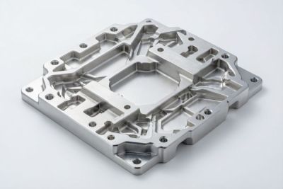
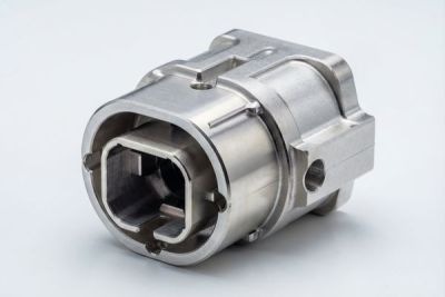
Why Vacuum Chamber Walls Need Mirror Finish to Ra 0.4 micrometer (2026 Guide)
You specified the pump, the gauge, and the gate valve. But the film on your wafers comes out patchy, the base pressure creeps up between runs, and the chamber takes forever to pump down on Monday morning. Nine times out of ten, nobody in the room is looking at the one surface that touches the vacuum everywhere at once: the interior wall of the chamber and the mating face of the lid. A rough machined wall is not a cosmetic issue - it is a hidden contamination and outgassing source that quietly taxes every cycle you run.
In this guide we walk through why vacuum chamber stainless mirror finishing is treated as a process requirement, not a polish, in serious thin-film and semiconductor work. We cover how CNC precision machining sets up the geometry that finishing protects, where Ra 0.4 micrometer actually matters versus where it is overkill, and a practical checklist you can hand a supplier before you release a purchase order. Everything below is written from a shop that has machined and mirror-finished stainless chambers and lids for years - the trade-offs are the ones we argue about with customers before the first bar is cut.
LusterControl is the brand of Dongguan Licun Technology Co., Ltd., a Dongguan source factory focused on CNC lathe stainless mirror finishing for 15 years since 2015. We run 60 CNC machines, a 4,000 square meter floor, and about 500,000 parts a month - so the numbers here are the ones our own inspection room signs off on, not catalog claims.
Table of Contents
- 1. Why Vacuum Chamber Stainless Mirror Finishing Matters for Thin-Film Yield
- 2. How CNC Precision Machining Shapes Vacuum Chamber Walls
- 3. Vacuum Chambers and Lids: The Outgassing and Particle Trap Problem
- 4. Tight Tolerance CNC for Vacuum Chamber Parts Machining
- 5. Stainless Steel Mirror Finishing vs Electropolishing for Chamber Interiors
- 6. Vacuum Chamber Parts Machining: Choosing 316L and Other Grades
- 7. Specifying Ra Targets on Vacuum Chamber Stainless Mirror Finishing
- 8. A Buyer's Checklist for Vacuum Chambers and Lids Sourcing
Semiconductor Equipment (Vacuum Chamber / Thin-Film) AI part image
Why Vacuum Chamber Stainless Mirror Finishing Matters for Thin-Film Yield
The wall is the largest vacuum surface you own - treat it like one.
A vacuum chamber interior can be the single largest surface exposed to your process gas. On a 300 mm chamber the wall area dwarfs the wafer area by orders of magnitude, so anything the wall releases - trapped moisture, machining oils, adsorbed ions - shows up in your base pressure and your film purity. A mirror-finished wall does three jobs at once: it shrinks the real surface area where gases adsorb, it removes the microscopic valleys that trap particles, and it lets you wipe or bake the surface clean instead of just displacing contamination from one groove to the next.
For thin-film and semiconductor applications the payoff is direct. Lower outgassing means a lower achievable base pressure and a shorter pump-down after a vent. Fewer particle traps means fewer flakes dropping onto a substrate during a hot cycle. And a smooth, cleanable wall means your Friday afternoon clean actually holds through the Monday morning pump-down instead of slowly bleeding contamination back into the chamber.
- Mirror finishing
- A mechanical or electrolytic process that brings a stainless surface to a near-specular, low-roughness state - at LusterControl our standard mirror line reaches Ra 0.6 micrometer and our top 8K line reaches Ra 0.2 micrometer.
- Ra (arithmetical mean roughness)
- The average absolute deviation of the surface profile from its mean line, in micrometers. Lower Ra means fewer peaks and valleys - and fewer places for gas and particles to hide.
- Outgassing
- The slow release of adsorbed or trapped gases from a material surface into the vacuum, which raises base pressure and contaminates the process.
Semiconductor Equipment (Vacuum Chamber / Thin-Film) AI part image
How CNC Precision Machining Shapes Vacuum Chamber Walls
Finishing only protects the geometry machining builds - get the geometry wrong and no polish saves you.
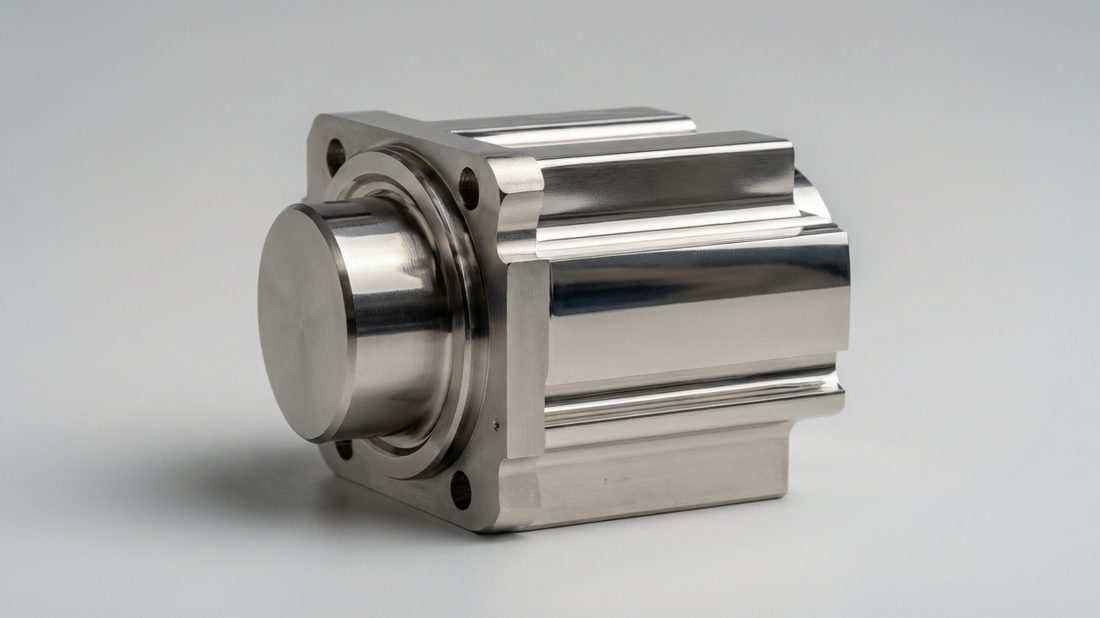
Before any mirror finishing happens, the chamber and lid have to be machined to a geometry that actually seals and registers. The mistake we see most often is treating the chamber as a simple turned can. A real vacuum chamber is a welded or monobloc body with a precision flange, a lid seat, port bosses, and internal features - every one of those needs tight tolerance CNC work before finishing can do its job. A mirror finish on a warped or poorly registered face is decoration, not engineering.
Step 1 - Material prep and roughing
We start from certified stainless bar or plate - usually 316L for low-carbon weldability and corrosion resistance - and rough out the body on CNC machining centers, leaving stock for finish passes. The principle here is simple: remove the bulk where it is cheap, and protect the datum faces that everything else references. For you this means the raw bore and flange are already true to a common datum, so the finishing passes later have a stable reference instead of chasing a moving one.
Step 2 - Precision boring and sealing-face machining
The sealing face of the flange and the lid seat are machined on a single setup wherever possible, holding flatness and perpendicularity so the knife-edge or O-ring seat is true. We hold positioning to +/-0.005 mm and measure the first article on a CMM with a full datum report. For you, a true sealing face is what lets a single gasket do its job; a face that is flat only 'on average' is what causes the slow helium leaks nobody catches until the chamber is in your line.
Step 3 - Finish pass and inspection
After machining, the interior wall is brought to the specified Ra. Mechanical mirror finishing (our standard line to Ra 0.6 micrometer, 8K line to Ra 0.2 micrometer) or electropolishing is applied depending on the spec, then the part is cleaned in a controlled environment and inspected. Every chamber we ship carries a helium-leak-test record with a traceable number and lot-level material traceability from raw bar to finished part - the evidence you need to close an audit, not just a photo.
Vacuum Chambers and Lids: The Outgassing and Particle Trap Problem
A mill mark is a microscopic trench - and trenches store contamination.
Every conventional machined surface is covered with tool marks: tiny peaks and valleys left by the cutter. Those valleys are exactly where water vapor, pump oil backstreaming residue, and process by-products like to hide. When you vent the chamber, they refill; when you pump down, they slowly release. The result is a base pressure that never quite reaches spec and a process gas that carries a little extra impurity every run.
Lids are half the problem and twice the temptation to skip. The lid seat and its underside see the same vacuum as the wall, and a lid that was finish-machined but never mirror-finished will shed the same particles and outgas the same way. Treating the wall and ignoring the lid is the classic half-measure we flag in DFM reviews.
| Surface condition | Relative outgassing | Particle trap risk | Cleanability |
|---|---|---|---|
| As-machined (Ra ~1.6 um) | High | High | Poor - grooves hide debris |
| Bead-blasted | Medium-High | Medium | Fair |
| Brushed / linished | Medium | Low-Medium | Good |
| Mirror (Ra 0.4 um) | Low | Very low | Excellent - wipes clean |
| 8K mirror (Ra 0.2 um) | Lowest | Negligible | Excellent - bakeable |
A vacuum system is only as clean as its roughest internal surface - and the lid is an internal surface.
Semiconductor Equipment (Vacuum Chamber / Thin-Film) AI part image
Tight Tolerance CNC for Vacuum Chamber Parts Machining
The seal is a tolerance budget - spend it where the vacuum depends on it.
A chamber does not need every dimension held to +/-0.005 mm; that would be expensive and pointless. What it needs is the tolerance budget concentrated on the relationships that actually hold vacuum: flange flatness, lid-to-body registration, port-axis perpendicularity, and the knife-edge or O-ring groove geometry. Everything cosmetic gets a commercial tolerance so the cost stays sane.
This is where tight tolerance CNC earns its keep. Holding the flange flat to a few microns and the lid seat true to the body axis means the gasket compresses evenly and the seal holds first try. Miss it and you are lapping by hand, re-cutting, or - worse - shipping a chamber that passes the bench test but leaks after a thermal cycle in your line.
| Feature | Why it matters | What we hold |
|---|---|---|
| Flange flatness | Even gasket compression, no leak path | 0.01 mm over the face |
| Lid seat perpendicularity | Lid registers true to body axis | 0.02 mm |
| Port axis perpendicularity | Fitting connectors without stress | 0.03 mm |
| O-ring groove / knife edge | Repeatable seal every closure | +/-0.01 mm |
| Wall thickness | Stiffness vs weight | Commercial +/-0.1 mm |
Pros
- Single-setup accuracy avoids datum shift
- CMM first-article report proves the seal geometry
- Lot traceability catches drift before a bad batch ships
- Concentrated tolerance keeps cost realistic
Cons
- Tight flatness needs slow, careful finishing passes
- Single-setup 5-axis or precision boring costs more than 3-axis re-fixturing
- Inspection overhead (CMM, helium leak) adds lead time
Stainless Steel Mirror Finishing vs Electropolishing for Chamber Interiors
Mechanical mirror and electropolish are not the same tool - know which one your process needs.
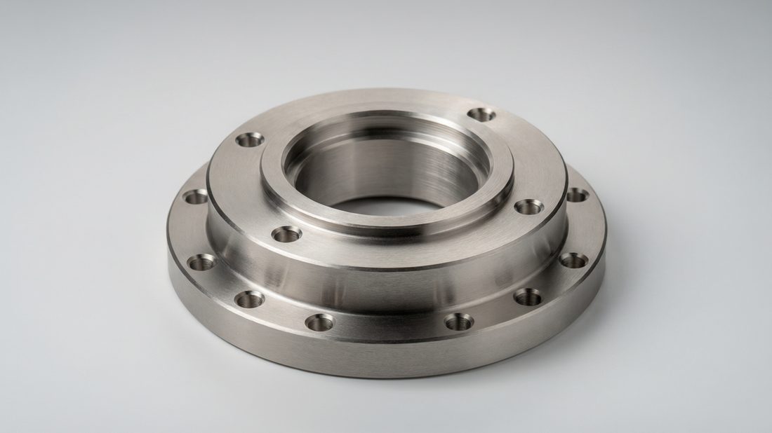
When buyers say 'mirror finish' they often mean either a mechanically polished surface or an electropolished one, and the two are genuinely different. Mechanical mirror finishing cuts and laps the surface to low Ra; it is predictable, fast, and great for geometries you can reach. Electropolishing dissolves a thin layer electrochemically, which can smooth hard-to-reach internal corners and leaves a passive, low-contamination surface - but it is chemistry-dependent and less controllable on complex shapes.
For most chambers we recommend mechanical stainless steel mirror finishing to Ra 0.4 micrometer as the baseline, stepping to Ra 0.2 micrometer (our 8K line) where the process is especially sensitive, and reserving electropolishing for internal features mechanical tools cannot reach evenly. The choice is about your process gas and your cleanability requirement, not about which sounds more advanced.
| Aspect | Mechanical mirror (Ra 0.4-0.2 um) | Electropolishing |
|---|---|---|
| Reach | Limited to accessible surfaces | Reaches internal corners |
| Control | High, repeatable | Chemistry-dependent |
| Passivation | Needs separate ASTM A967 passivation | Self-passivating layer |
| Lead time | Shorter | Longer, more setup |
| Best for | Walls, flanges, lids | Complex internal cavities |
- Choose mechanical mirror finishing if your chamber is mostly open walls, flanges, and a flat lid you can reach and inspect.
- Choose electropolishing if you have deep internal features mechanical tools cannot polish evenly.
- Choose both if the part has reachable walls plus unreachable cavities - we often combine them.
- Choose neither-overkill if your process is non-UHV and Ra 0.8 micrometer already meets your base-pressure target.
Semiconductor Equipment (Vacuum Chamber / Thin-Film) AI part image
Vacuum Chamber Parts Machining: Choosing 316L and Other Grades
Grade is a contamination and weldability decision before it is a strength decision.
For vacuum chamber parts machining the default is 316L stainless: low carbon so it welds without sensitization, excellent corrosion resistance, and clean enough for most semiconductor and thin-film work. The 'L' matters - standard 316 has enough carbon that welding can precipitate chromium carbide at the grain boundaries, which both weakens corrosion resistance and can be a contamination path. If your chamber is welded, 316L is the safe call unless you have a specific reason otherwise.
There are real alternatives. 304 is cheaper and fine for many non-critical or rough-vacuum housings. 6061 aluminum is common for non-UHV frames and brackets because it is light and easy to machine, though it outgasses more and is not for the process volume. Titanium appears in corrosive or high-purity niches but is costly to machine. The grade decision should follow your base-pressure target and your weld plan, not the price of the bar.
| Grade | Use it for | Watch out for |
|---|---|---|
| 316L stainless | Welded UHV / semiconductor chambers | Cost vs 304; still needs passivation |
| 304 stainless | Rough-vacuum housings, brackets | Lower corrosion resistance, carbon risk if welded |
| 6061 aluminum | Non-UHV frames, lightweight parts | Higher outgassing; not for process volume |
| Titanium (Gr2/5) | Corrosive or ultra-high-purity niches | 2-3x machining cost, heat management |
Specifying Ra Targets on Vacuum Chamber Stainless Mirror Finishing
Ra 0.4 micrometer is a target, not a reflex - specify it where it earns its cost.
Not every surface in a chamber needs Ra 0.4 micrometer. Specifying mirror finish everywhere is the fastest way to inflate cost without improving your process. The disciplined approach is to map Ra to function: the interior wall and the gate-valve seat, which directly contact or shed into the vacuum, get the tight spec; external flanges and cosmetic bosses can stay at a brushed or machined finish.
As a rule of thumb we see Ra 0.4 micrometer as the workhorse chamber-wall target, stepping to Ra 0.2 micrometer (our 8K line) only where the process is especially sensitive - very low base-pressure targets, or where a single flake ruins an expensive run. For rough-vacuum or non-process volumes, Ra 0.8 micrometer is usually plenty, and pushing lower just adds cost and lead time.
| Surface | Recommended Ra | Why |
|---|---|---|
| Interior wall (process volume) | 0.4 um | Low outgassing, wipe-clean |
| Gate valve / seat | 0.4 um | Particle and leak control |
| Lid underside / seat | 0.4 um | Same vacuum as wall |
| External flange (non-seal) | 0.8-1.6 um | Cosmetic, no process contact |
| Deep internal cavity | 0.2-0.4 um (electropolish) | Unreachable by tools |
- State Ra per surface, not one number for the whole part
- Decide mechanical mirror vs electropolish per feature
- Specify passivation per ASTM A967
- Agree the inspection method (profilometer trace, not 'looks shiny')
- Confirm cleanroom handling and helium-leak documentation

Semiconductor Equipment (Vacuum Chamber / Thin-Film) CNC precision component
A Buyer's Checklist for Vacuum Chambers and Lids Sourcing
Hand this to a supplier and the tire-kickers filter themselves out.
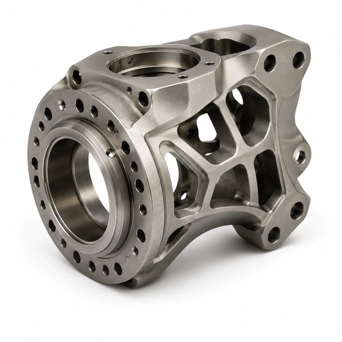
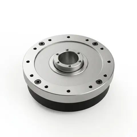
Sourcing vacuum chambers and lids is less about finding the cheapest machine and more about finding a shop that understands vacuum intent - that a leak is a spec failure, not an inconvenience, and that the lid is as much a vacuum surface as the wall. The list below is what we are happy to answer with data, and it is the fastest way to tell a real precision source from a broker with a logo.
- Request the cert stack: ISO 9001 at minimum, ISO 13485 system a strong plus
- Demand material certs traceable to the heat lot (316L, low carbon)
- Confirm single-setup capability so sealing faces stay on one datum
- Get a CMM first-article report with full datum references, not a photo
- Require a helium-leak-test record with a traceable number per chamber
- Agree coated/passivated vs bare tolerances before quoting
- Verify lot-level traceability from raw bar to finished part
- Ask who cleans and packages the part, and in what environment
Semiconductor Equipment (Vacuum Chamber / Thin-Film) CNC precision component
Semiconductor Equipment (Vacuum Chamber / Thin-Film) CNC precision component
Semiconductor Equipment (Vacuum Chamber / Thin-Film) CNC precision component
Semiconductor Equipment (Vacuum Chamber / Thin-Film) CNC precision component
FAQ: vacuum chambers and lids & Semiconductor Equipment (Vacuum Chamber / Thin-Film) Buyer Questions
A: An as-machined wall is covered with microscopic tool marks that trap moisture, process residues, and particles, and slowly outgas into the vacuum. A mirror finish to Ra 0.4 micrometer shrinks the real surface area, removes those traps, and lets you clean or bake the wall effectively - which lowers base pressure and cuts particle defects in thin-film and semiconductor runs.
A: No. The disciplined approach specifies Ra per surface: the interior wall, gate-valve seat, and lid underside get Ra 0.4 micrometer because they contact or shed into the vacuum, while external non-sealing flanges can stay at Ra 0.8-1.6 micrometer. Step to Ra 0.2 micrometer only where the process is especially sensitive. Specifying mirror everywhere just adds cost.
A: For a welded chamber choose 316L. Its low carbon content avoids chromium-carbide sensitization at the weld, which protects both corrosion resistance and cleanliness. Standard 304 is cheaper and fine for non-welded or rough-vacuum housings, but welding it risks sensitization that can fail a clean audit.
A: Mechanical mirror finishing to Ra 0.4 micrometer is the predictable baseline for reachable walls, flanges, and lids. Electropolishing reaches internal corners mechanical tools cannot and leaves a passive surface, but it is chemistry-dependent. Many chambers use both: mechanical on open surfaces, electropolish on deep internal cavities.
A: At minimum: material certs traceable to the heat lot, a CMM first-article report with full datum references, a profilometer Ra trace on critical surfaces, passivation records per ASTM A967, and a helium-leak-test record with a traceable number. Lot-level traceability from raw bar to finished part should be standard, not requested.
A: Yes, and we recommend it. Machining the body and lid on a common datum and mirror-finishing both sealing interfaces together is what guarantees the lid registers true to the body axis and the seal holds on the first closure. Send us your drawing for a free DFM review via our <a href='https://www.lustercontrol.com/sendinquiry.htm'>inquiry page</a> and we will flag where the tolerance budget should be spent.
Send us your chamber or lid drawing for a free DFM review - we will show you where Ra 0.4 micrometer actually earns its cost, which sealing faces need single-setup accuracy, and whether mechanical mirror or electropolish fits your process. Let's cut the first article and close the leak on the first try.
Request a Free CNC Quote