CNC Heat Sinks: Materials & Fin Design for 2026
If you specify CNC heat sinks, you have probably picked a size from a catalog and moved on. That is the mistake most thermal budgets pay for later. The sink that looks right on the datasheet can still cook your board because the material, the fin geometry and the flatness against the device were never tied to the actual watts your part dissipates. A heat sink is not a block with ribs — it is a thermal path with a machining budget attached.
This 2026 buyer's guide is written from the purchasing side of the table. We walk through why material choice decides thermal performance before anything else, how aluminum CNC machining became the default for most sink bodies, where EMI shielding and electronic housings overlap with the sink, and what tight tolerances connector machining actually demands at the I/O boundary. By the end you should be able to put the right material, fin spec and flatness number on the drawing instead of hoping the catalog part fits.
The practice described here is how Dongguan Licun Technology (brand LusterControl) machines thermal and enclosure parts daily — the same 60-machine, 4,000 m2 Dongguan source factory that holds +/-0.005 mm on aluminum, stainless and connector work under ISO 9001 and ISO 13485 control, with IATF 16949 in progress.
Table of Contents
- 1. CNC Heat Sinks: Why Material Choice Decides Thermal Performance
- 2. Aluminum CNC Machining: The Default for Heat Sink Bodies
- 3. EMI Shielding: When the Housing Does Double Duty
- 4. Electronic Housings: Machining the Enclosure Around the Sink
- 5. Connector Machining: Tight Tolerances at the I/O Boundary
- 6. CNC Heat Sinks vs Extrusion: Which Process for Your Volume?
- 7. Aluminum CNC Machining: Fin Design and Flatness Limits Buyers Must Specify
- 8. EMI Shielding Buyer's Checklist: What to Put on the Drawing
- 9. Electronic Housings and Connector Machining: Red Flags in a Supplier
Electronics&Communication AI part image
CNC Heat Sinks: Why Material Choice Decides Thermal Performance
The metal moves the heat, not the shape alone.
Before you argue about fin count, settle the material. Thermal conductivity is the property that actually carries heat from the device to the air, and it varies more across common sink metals than most buyers expect. Pick a material whose conductivity matches your watt load and your fin design has something to work with. Pick wrong and no amount of ribbing saves you — the heat simply cannot get out of the base fast enough.
What actually dissipates the heat
Two numbers matter to a buyer: thermal conductivity (how fast heat spreads through the metal) and the contact resistance at the device interface. A sink with high conductivity but a warped base leaves a micrometer air gap under the device, and air is a thermal insulator. So material choice and the flatness we discuss later are the same conversation, not two.
- Heat sink
- A passive metal component that spreads heat from a hot device into a larger surface area so air can carry it away.
- Thermal conductivity
- A material property (W/mK) describing how fast heat moves through it; higher means the sink pulls heat away from the device faster.
- Interface gap
- The micrometer-scale air gap between device and sink base that quietly throttles heat transfer no matter how good the fins are.
| Material | Thermal conductivity (W/mK) | Machinability | Where it earns its cost |
|---|---|---|---|
| Aluminum 6061 | about 167 | Excellent, cheap to mill | Most consumer and comms sinks |
| Aluminum 6063 | about 201 | Excellent, smoother anodize | Exposed, cosmetic sinks |
| Copper C110 | about 390 | Heavy, slower to cut | High-watt density, tight spaces |
| Stainless 304 | about 16 | Hard, work-hardens | Structural only, not a primary sink |
Electronics&Communication AI part image
Aluminum CNC Machining: The Default for Heat Sink Bodies
6061 and 6063 win on the three numbers that matter.
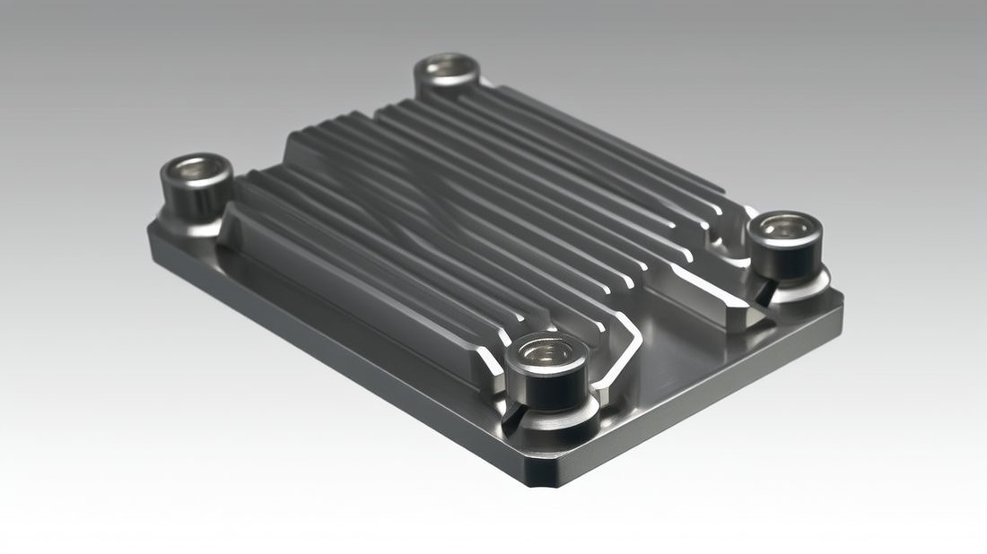
For the large majority of CNC heat sinks, aluminum CNC machining in 6061 or 6063 is the right call. It conducts well enough, machines cleanly at speed, anodizes to a durable finish, and keeps the part light — which matters when the sink is bolted to a portable or rack-mount device. The reason you see aluminum sinks everywhere is not fashion; it is the best trade of conductivity, cost and machinability.
Why 6061 and 6063 win for most sinks
- Conductivity high enough for the vast majority of comms and consumer watt loads
- Excellent chip evacuation and tool life on a production CNC cell
- Anodizing takes well, so the sink survives handling and corrosion
- Low density keeps the finished assembly light and easy to mount
- Readily available bar and plate stock with full mill certs for traceability
On a turn-mill or 5-axis cell, the base, the fins and the mounting features of a sink are cut in one coordinated flow, so the fin root stays referenced to the same datum as the device face. That single-setup discipline is what keeps a sink flat where it matters and square where it bolts. LusterControl runs aluminum sink bodies on the same rigid cells used for medical and automotive work, where a thermal or sealing face that drifts is never an option.
| Process | Best for | Lead time | Tooling cost | Geometry freedom |
|---|---|---|---|---|
| Aluminum CNC machining | Low-to-mid volume, complex fins, tight flatness | Short, no tooling | Low (no die) | Very high |
| Extrusion | High volume, straight constant fins | Long die lead | High die cost | Limited (straight only) |
| Die casting | Very high volume, simple shapes | Long tooling | Very high | Medium |
EMI Shielding: When the Housing Does Double Duty
The enclosure can be the shield if you machine it right.
Many electronics buyers treat EMI shielding as a coating they spray on at the end. That is fragile thinking. A shield only works if it forms a continuous conductive path with no gaps at the seams, and a machined electronic housing can deliver that path by design rather than by afterthought. When the sink and the housing are part of the same assembly, the shielding conversation starts on the drawing, not in the plating bath.
The conductive path is the whole game
EMI leaks through the seams where two metal faces meet imperfectly. If the housing halves are milled to a tight seam and the gasket or conductive coating lands on a flat, clean face, the shield closes. If the seam is wavy or the coating is applied over a rough, oily surface, the leak stays. The machining sets up whether the shield can ever work.
- EMI shielding
- Blocking unwanted electromagnetic interference so your device and its neighbors behave, usually via a continuous conductive enclosure.
- Conductive gasket
- An elastomer or mesh strip that closes the seam between two shielded faces while staying electrically continuous.
- Seam continuity
- The unbroken conductive path around every joint of the enclosure — the property that actually stops leakage.
| Approach | When it fits | Risk if machined poorly |
|---|---|---|
| Machined tight seam + gasket | Split housings, serviceable gear | Leaks if seam flatness slips |
| Conductive coating (paint/plate) | Complex internal shields | Thin film scratches, then gaps |
| Formed-in gasket groove | High-volume sealed boxes | Groove out of position = no seal |
Electronics&Communication AI part image
Electronic Housings: Machining the Enclosure Around the Sink
The box and the sink share one tolerance stack.
An electronic housings program rarely ships a sink alone — it ships a sink bolted inside an enclosure, and the two share a tolerance stack. If the housing pocket that receives the sink base is cut a few tenths out, the sink rocks, the interface gap opens, and the thermal path you paid for collapses. The housing is not decoration around the sink; it is the other half of the thermal and shielding path.
Tolerance stack-up between sink and housing
On a modern cell a touch probe measures the pocket and the sink reference in place, the controller corrects the next cut before unchuck, and the assembly ships with a CMM report on both halves. That closed loop is what turns 'looks close enough' into 'fits every time.' LusterControl couples it with incoming-batch traceability, so the aluminum behind your housing is documented and any deviation ties to a lot, not a finger-point.
| Fit feature | What it controls | Typical spec on our cells |
|---|---|---|
| Sink-pocket depth | Contact pressure at device | ±0.02 mm |
| Pocket flatness | Interface gap, thermal path | ±0.005 mm |
| Bolt pattern position | Sink squareness to board | ±0.01 mm |
| Seam face flatness | EMI shield continuity | ±0.01 mm |
Connector Machining: Tight Tolerances at the I/O Boundary
The connector is where the box meets the world.
Connector machining sits at the boundary where your electronic housings meet cables, boards and mates. Get it wrong and the connector wobbles, the contact resists, or the seal leaks — even when everything inside the box is perfect. Because the connector is the part that is actually handled, plugged and unplugged, its tolerances are not optional cosmetics; they are the user's first impression of your build quality.
Why connector features need ±0.005 mm
A connector cavity that is a few microns out of position forces the mating plug to skew, which wears the contacts and eventually loosens the seal. Holding the cavity, the pin holes and the sealing face to +/-0.005 mm means the mate drops in straight every time and the gasket compresses evenly. Swiss-type turning and turn-mill cells are built for exactly this — small, repeatable, high-volume precision.
- Probe the housing datum and the connector boss in one setup
- Cut the cavity, pin holes and sealing face referenced to that datum
- Verify pin-hole position and seal face with the on-machine probe
- Ship with CMM report and first-article data under ISO 9001 control
Electronics&Communication AI part image
CNC Heat Sinks vs Extrusion: Which Process for Your Volume?
Match the process to the volume, not the catalog.
Buyers often default to extruded sinks because they are cheap per piece — forgetting the die lead time and the straight-fin limitation. CNC heat sinks cost more per unit at high volume but unlock any fin geometry, including pin and staggered patterns, and they need no tooling buy. The honest question is not 'which is cheaper' but 'which fits my volume and my fin shape.'
| Factor | CNC heat sinks | Extruded sinks |
|---|---|---|
| Fin geometry | Any: pin, staggered, angled | Straight constant cross-section only |
| Tooling buy | None | Extrusion die, upfront cost |
| Time to first part | Days | Weeks for the die |
| Unit cost at 50k | Higher | Lower |
| Best fit | Prototype to mid volume, complex fins | High volume, simple fins |
Pros
- No tooling cost, fast first article
- Fin geometry is free — design what thermals need
- Easy to revise the sink between revisions
Cons
- Higher per-unit cost at very high volume
- Thin tall fins can need finer tooling and more cycle time
- Anodize adds a step if cosmetics matter
Aluminum CNC Machining: Fin Design and Flatness Limits Buyers Must Specify
Fins and flatness are where drawings usually fail.
Two specs decide whether your aluminum CNC machining sink actually works: the fin geometry and the base flatness. Buyers tend to over-specify fin count and under-specify flatness. A sink with fifty perfect fins on a warped base still throttles, because the device never touches the metal evenly. The flatness at the interface is the spec that protects every fin you paid for.
Fin pitch, height and the tool
There is a real machining floor on fin pitch: too tight and the end mill cannot clear chips, so the fin walls score and the thermal surface suffers. Taller, thinner fins look great on paper but can chatter and drift. The right fin design balances surface area against what a rigid cell can hold repeatedly. We flag impossible fins in DFM rather than quote a part we cannot hold.
| Fin parameter | Machinable range | What breaks if pushed |
|---|---|---|
| Fin pitch | >= 1.0 mm practical | Chip packing, scored walls |
| Fin height / thickness | up to ~10:1 height ratio | Chatter, dimensional drift |
| Base flatness | ±0.005 mm achievable | Interface gap, lost cooling |
| Base finish | Ra <= 0.6 µm, 8K Ra 0.2 µm option | Air gap if left rough |
Electronics&Communication AI part image
EMI Shielding Buyer's Checklist: What to Put on the Drawing
Seven items that keep the shield real.
- Material grade and mill cert for the aluminum or stainless on the lot
- Base flatness number at the device interface, not just a finish word
- Fin pitch and height limits the shop can actually hold
- Seam flatness and gasket groove position for EMI shielding
- Connector cavity and pin-hole position tolerance, in microns
- Anodize or passivation (ASTM A967 for stainless) if the path needs it
- Quality paperwork: CMM report, first-article, batch traceability
Common mistakes buyers make
- Writing 'heat sink' with no material or flatness, so quotes diverge wildly
- Specifying fin count but forgetting the pitch the tool can clear
- Treating EMI shielding as a coating with no seam geometry called out
- Leaving the connector cavity tolerance to 'standard precision'
- No batch traceability, so a field failure cannot be tied to stock
Send those seven items and a supplier can run a free DFM review and tell you which fins are real, which flatness number protects your thermal path, and where the shield seam must land. That conversation before cutting beats a thermal report after shipment. Start one on our inquiry page, or read how we handle flatness on power parts in our EV thermal management guide.
Electronic Housings and Connector Machining: Red Flags in a Supplier
What a qualified thermal-and-enclosure shop shows without asking.
- No base flatness reading at the device interface you specified
- No measured connector cavity position, only a blanket tolerance
- No mill cert for the aluminum grade on the lot
- EMI shielding treated as a coating with no seam geometry shown
- No batch traceability tying a field failure to stock and process
- Vague 'high precision' claims with no micron band or datum
With 500K parts per month across medical, automotive, semiconductor and electronics work, the same cells that build your aluminum sink and enclosure also run parts held to medical and automotive discipline — so your thermal and connector parts leave production-ready, not prototype-lucky. Learn more on our about page or browse related capability notes on our blog.
Electronics&Communication AI part image
Electronics&Communication AI part image
Electronics&Communication AI part image
Electronics&Communication AI part image
FAQ: CNC heat sinks & Electronics&Communication Buyer Questions
A: For most comms and consumer watt loads, 6061 aluminum (about 167 W/mK) is the right default: it conducts well, machines fast and anodizes cleanly. Step up to 6063 for a smoother cosmetic anodize, or to copper (about 390 W/mK) only when watts per square centimeter leave aluminum no headroom. Stainless is a structural choice, not a primary sink metal.
A: Match the process to volume and fin shape. CNC heat sinks need no tooling, reach any fin geometry including pin and staggered patterns, and ship a first article in days — ideal for prototype-to-mid volume and designs that will revise. Extrusion wins only at 50k+ units with a constant straight fin and no planned change, where the per-unit cost drops below CNC.
A: Specify a number, not a word. LusterControl holds the device-interface face to +/-0.005 mm, with a base finish of Ra <= 0.6 micrometer standard and an 8K mirror Ra 0.2 micrometer option. A flat, slightly rougher base beats a mirror base that is wavy, because the device seals to the shape first and the finish second.
A: The shield is the geometry, not just a coating. A machined tight seam and a correctly positioned gasket groove form the continuous conductive path that blocks interference; a spray coating applied over a wavy seam still leaks. Specify seam flatness and gasket-groove position so the shop machines the shield, not just plates it.
A: The connector is the handled, plugged boundary of your electronic housings. A cavity or pin-hole pattern a few microns out forces the mate to skew, wears contacts and loosens the seal. Holding the cavity, pin holes and sealing face to +/-0.005 mm lets the mate drop in straight every time and the gasket compress evenly.
A: No base flatness reading at the interface, no measured connector cavity position, no mill cert for the aluminum grade, EMI shielding treated as a coating with no seam geometry, and no batch traceability. Any of those means the shop is quoting a shape, not a sealed, cooled, shielded assembly.
Send us your heat sink, electronic housing or connector drawing for a free DFM review and a realistic lead-time quote — we will flag the fins, flatness and shield seams that actually decide whether your part stays cool and compliant.
Request a Free CNC Quote