Turn-Mill Composite vs Re-Chucking: Motor Shaft Machining Cost Guide (2026)
A three-electric program rarely fails because a motor shaft missed a diameter. It fails because two diameters that mattered to each other were cut in two fixtures, and the small offset between them grew into a vibration, a bearing preload problem, or a gear-mesh whine that only shows up after the unit is assembled. If you source motor mating parts and transmission structures, the decision that quietly decides all of this is not the material grade or the headline unit price — it is whether the critical features share one datum frame or are handed between machines.
This guide is written for the drive engineer and the purchase lead who have to defend that decision in 2026. We compare turn-mill composite against conventional CNC turning with re-chucking, not as a technology contest but as a cost and risk structure. We look at what one-setup motor shaft machining does to coaxiality and cumulative error, where the money and the lead time actually go, and what tight tolerance CNC looks like when it has to hold across a production run rather than on a single sample.
We will be honest about the trade-offs: a split turning route is still the right answer for some parts, and we will say when. Cost and lead time are discussed as drivers and principles, not as fixed prices — your geometry, material and volume set the number, and any supplier who quotes before reading the drawing is guessing. Every capability figure cited below is our own: LusterControl (Dongguan Licun Technology Co., Ltd.) was founded in 2015, has 15 years of CNC precision-machining focus with stainless-steel mirror finishing at its core, runs 60 CNC machines in a 4,000 m² plant (2026 expansion; the former 2,000 m² figure is obsolete), holds ±0.005 mm in production and ships up to 500,000 parts per month.
The quality backdrop is stated plainly because buyers need it: ISO 9001 certification is held, an ISO 13485 quality system is established with certification advancing, and an IATF 16949 application is in progress. Nothing in this guide is an industry average or a competitor claim — it is a framework you can use to interrogate any supplier, including us.
Table of Contents
- 1. Why Motor Mating Parts and Transmission Structures Decide Three-Electric Reliability (2026)
- 2. What Turn-Mill Composite Machining Does in a Single Setup
- 3. Turn-Mill Composite vs CNC Turning Re-Chuck: 7 Cost Factors Compared
- 4. Motor Shaft Machining: Coaxiality and Cumulative Error in Practice
- 5. Tight Tolerance CNC: Sustaining ±0.005 mm at Volume
- 6. CNC Precision Machining Cost Model: Where the Money Really Goes
- 7. Which Route Fits Your Motor Mating Parts and Transmission Structures?
- 8. Buyer's Checklist: Vetting a Turn-Mill Composite Machining Supplier
- 9. Quality Framework Behind CNC Precision Machining for EV Programs
- 10. Common Mistakes in Motor Shaft Machining Sourcing
New Energy Vehicles (Three Electric) CNC precision component
Why Motor Mating Parts and Transmission Structures Decide Three-Electric Reliability (2026)
In a drive unit, the relationship between features matters more than any single feature.
An electric drive unit is a stack of precision relationships. The motor shaft carries a bearing journal, a shoulder, a sealing land, a keyway or spline, and a mating interface to the reducer. The reducer shaft carries its own set of coaxial features, and the housing that holds them has bores that must align with both. A buyer looking at motor mating parts and transmission structures sees a list of turned diameters; the assembly sees a chain of coaxiality requirements. When that chain drifts, the symptoms are familiar to any drive engineer: bearing noise, uneven preload, seal weep, gear-mesh error and a durability test that fails late enough to be expensive.
The commercial trap is that each feature looks acceptable on its own. A caliper check passes. A diameter is within tolerance. And yet the part is wrong, because the tolerance that mattered was a relationship between two features cut in different setups. That is why the sourcing decision on these parts belongs in engineering, not only in purchasing: the route chosen at RFQ decides whether the datum chain is protected or accumulated.
- Motor mating parts
- Machined features on a motor or reducer that locate and transmit load between components — journals, shoulders, pilot diameters, seal lands, keyways and splines.
- Transmission structure
- The shaft, hub and interface parts that carry torque through a reduction stage, where coaxial relationships govern mesh quality and bearing life.
- Coaxiality
- The condition in which two or more cylindrical features share a common axis; the tighter the relationship, the more sensitive it is to re-clamping between machining operations.
- Cumulative error
- The sum of small positioning errors introduced each time a part is removed and re-fixtured; individually trivial, collectively the reason an assembled drive unit is out of tolerance.
We set out the process discipline behind these parts in our Dongguan plant overview; this guide stays on the single decision in front of you — one setup or two — and what it costs when it is wrong.
A shaft does not fail because a diameter was 0.01 mm off. It fails because two diameters that should share an axis did not.
New Energy Vehicles (Three Electric) CNC precision component
What Turn-Mill Composite Machining Does in a Single Setup
The principle is simple: clamp once, and machine every related feature in the same coordinate system.
The principle: one datum frame, not a chain of handoffs
Turn-mill composite machining combines turning and live-tool milling on one platform, so the blank is clamped once and the spindle, live tooling and measuring probes all work from a single reference. On a motor shaft, the turning operation produces journals and shoulders; live tooling cuts flats, keyways, ports or cross-holes; a finishing pass completes the seal land. Because the coordinate system never changes, the positional relationship between those features is determined by the program rather than by how accurately an operator re-seats the part tomorrow morning.
The machine: what the platform contributes
The hardware that makes this repeatable is a turning centre with live tooling, a reliable workholding scheme and in-process probing where the feature warrants it. On our floor these cells sit alongside 5-axis capability and Swiss-type machines, so the route follows the geometry: long, slender shafts and small-diameter parts often favour Swiss-type turning, while larger motor mating parts and ported bodies favour a turn-mill cell. The point is not that one machine is universally better — it is that the critical datum features stay together in one clamping wherever the part allows it.
The result: what changes for your part
For the buyer, one-setup machining removes the largest source of variation in a shaft program: the re-clamp. First-article repeatability improves because the program, not the fixture, sets the relationship. Inspection effort shifts from re-verifying every relationship to confirming that the process stayed in control. And a design change is easier to absorb, because modifying a toolpath does not require re-proving a chain of fixtures. This is the foundation of tight tolerance CNC on rotational parts — the tolerance is held because the datum frame is stable, not because the inspection department rejects the outliers.
- Stability: the axis of the journal and the axis of the mating feature are cut under the same clamping.
- Repeatability: the same program reproduces the same relationship across shifts and across batches.
- Traceability: one route, one setup record, one place to look when a question arises months later.
A worked discussion of route selection across other demanding parts is in our CNC precision machining technical guides.
Turn-Mill Composite vs CNC Turning Re-Chuck: 7 Cost Factors Compared
The cheaper hourly rate is not the cheaper part if the datum frame has to be rebuilt twice.
This comparison is deliberately about structure rather than a fixed price. Your quote depends on drawing, material, batch size and inspection level; a responsible supplier will not name a number before reading them. What can be compared honestly is the cost driver behind each route, so you can see where a low quote is likely to reappear later as scrap, rework or an expedited shipment.
| Factor | Turn-mill composite, one setup | CNC turning with re-chucking |
|---|---|---|
| Journal-to-mating-feature coaxiality | Set by one datum frame; ±0.005 mm production capability where the drawing requires it | Limited by re-clamping repeatability; offset varies part to part |
| Setup count | One primary clamping for related features | Two to three handoffs between turning, milling and drilling |
| Cumulative error | Effectively removed from the feature relationship | Added at every re-fixture, invisible until assembly |
| First-article repeatability | Program-driven; reproducible across shifts | Operator- and fixture-dependent |
| Cycle time structure | Higher machine content per part, fewer transfers | Lower machine rate, more handling and queue time |
| Inspection content | Focus on process control plus critical-feature checks | More relationship checks to catch datum drift |
| Cost exposure | Predictable cost; investment is in machine time | Low visible part cost, higher downstream risk |
- 1. Coaxiality. If two diameters must share an axis, one setup is the most direct way to hold that relationship. Re-chucking makes it a matter of fixture accuracy and operator care on every part.
- 2. Setup count. Count the handoffs on the quoted route. Each one is an opportunity for cumulative error and an extra queue in the schedule.
- 3. Cumulative error. This is the cost that never appears on a quote: small offsets that add up to a shaft that assembles poorly.
- 4. Repeatability. A first article proves a process once. Ask what the third shift produces on a Friday afternoon — one route answers with program control, the other with a fixture record.
- 5. Cycle time. One-setup routing concentrates time on the machine; split routing distributes it into handling, waiting and re-inspection. Lead time follows the route, not the machine's spindle rate.
- 6. Inspection. A controlled datum frame reduces the number of relationships you must re-measure; a split route increases them. That inspection burden is real cost even when it is buried in overhead.
- 7. Risk. The visible price difference is usually small next to a line stoppage, a durability retest or a held shipment. Price the failure mode, not just the part.
New Energy Vehicles (Three Electric) CNC precision component
Motor Shaft Machining: Coaxiality and Cumulative Error in Practice
Motor shaft machining is where a datum decision becomes a durability result.
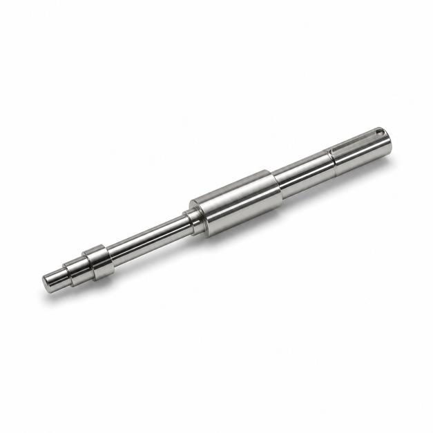
A motor shaft and its mating reducer shaft are not simple cylinders. They carry bearing journals, thrust shoulders, seal lands, keyways or splines, sometimes a threaded end, and often a pilot diameter that locates the next component. Each of these has a tolerance, but the ones that decide assembly behaviour are the ones that reference a common axis. When the bearing journal and the pilot are cut in different fixtures, their offset is small enough to pass a routine check and large enough to tilt a bearing race. Over a duty cycle, that tilt becomes heat, noise and premature wear.
This is the practical reason our motor shaft and reducer shaft programs favour one-setup turning: a single clamping reduces cumulative error between the features that must agree. The principle applies equally to the transmission structures around the shaft — hubs, coupling ends and interface plates that locate on the same axis.
| Shaft feature | Why the relationship matters | What re-chucking risks | One-setup approach |
|---|---|---|---|
| Bearing journal to pilot diameter | Defines the rotational axis for the whole assembly | Offset tilts the bearing race | Both diameters turned in one clamping |
| Seal land to journal | Controls lip contact and seal life | Runout causes weep after cycling | Finish land under the same datum |
| Keyway or spline to axis | Sets torque transfer and balance | Positional drift changes mesh and balance | Live-tool cut in the turning coordinate system |
| Thrust shoulder to axis | Locates axial load path | Face runout concentrates preload | Facing and turning in one setup |
| Threaded end to pilot | Affects assembly stack and clamp load | Misalignment adds assembly stress | Program-controlled relationship |
Cumulative error is the sum of every handoff
Each re-clamping introduces a small positioning error. On a shaft with four related features and three handoffs, the buyer does not get three small errors — the buyer gets the worst combination of them in the assembled unit. Because these offsets are systematic only in aggregate, they are hard to catch with a sampling plan and easy to miss in a first-article report that measures diameters one at a time. The remedy is not more inspection at the end; it is fewer handoffs at the source.
Tight Tolerance CNC: Sustaining ±0.005 mm at Volume
A tolerance on the first article is a claim. A tolerance on the ten-thousandth is a process.
Tight tolerance CNC is often sold as a number. The number only means something when it survives shift changes, tool wear and batch changes. On motor mating parts and transmission structures, the features that demand the tightest control are usually small areas on a larger body — a seal land, a pilot, a shoulder face — so thermal drift and clamping force move them more than they move a general dimension. Holding ±0.005 mm in production is therefore a question of process design, not of inspection luck.
What a controlled process looks like
A controlled route begins with a stable datum, keeps related features in one setup where the geometry allows, manages tool life so a finishing pass is not taken with a worn insert, and checks the critical feature at defined intervals. Incoming bar stock is identified by batch and the identification travels with the parts. The result is a record you can show an auditor: which route made the part, which tool finished the critical feature, and what was measured when.
| Capability check | What to ask | What a weak answer sounds like |
|---|---|---|
| Held tolerance | Is ±0.005 mm held in production or reached on samples? | 'We can hit it on the first piece.' |
| Datum control | Which single setup holds the journal relative to the pilot? | 'We line them up at inspection.' |
| Tool-life management | When is the finishing tool changed? | 'When the operator sees an issue.' |
| Batch traceability | Can a batch be traced to incoming material? | 'We don't normally keep that.' |
| Repeatability | What does the critical feature measure across shifts? | 'It depends who is running it.' |
- Tight tolerance CNC
- Computer-numerical-control machining held to a narrow dimensional band — ±0.005 mm in our production — verified at the feature and sustained across a batch.
- Datum frame
- The reference surfaces from which a part's features are dimensioned; keeping related features in one frame avoids accumulated setup error.
- Traceability
- The ability to link a finished part to its incoming material batch, process route, inspection records and test results.

New Energy Vehicles (Three Electric) CNC precision component
CNC Precision Machining Cost Model: Where the Money Really Goes
The visible price is only one line in the cost of a shaft program.
Buyers often ask which route is cheaper. The honest answer is that CNC precision machining cost is a structure, not a rate: machine time, handling, fixtures, inspection, scrap exposure and schedule risk all move together, and their balance changes with volume and geometry. We do not publish fixed prices because a drawing we have not seen can change every one of those terms. What we can do is show where the money goes so you can read a quote intelligently.
| Cost element | One-setup turn-mill route | Split turning and re-chuck route |
|---|---|---|
| Machine time | Concentrated on one platform; higher content per part | Lower rate per operation, more operations |
| Workholding | Fewer fixtures, simpler fixture proof | More fixtures, each needing validation |
| Handling and queue | Minimal transfers between operations | Multiple transfers and waiting time |
| Inspection | Process control plus critical-feature checks | More relationship checks to catch datum drift |
| Scrap and rework | Drift caught earlier in the route | Offset may be found only at assembly |
| Schedule risk | Shorter, more predictable route | More dependencies, more expedite exposure |
| Best economic fit | Coaxial, sealing or multi-feature shafts | Simple parts with loose positional tolerances |
- Hidden cost one: rework time spent chasing a relationship error that a fixture introduced.
- Hidden cost two: extra inspection added after a supplier cannot prove process control.
- Hidden cost three: a delayed launch while a datum problem is diagnosed at assembly.
- Hidden cost four: a durability retest caused by bearing preload drift that traced back to coaxiality.
- Hidden cost five: engineering time spent re-qualifying a part after its production route quietly changes.
Lead time follows the same logic: it is driven by the number of operations and the number of times a part waits, not by the promise on a quotation. If you want a route-specific answer for your part, send us the drawing for a review and we will identify which features actually need one-setup control.
Which Route Fits Your Motor Mating Parts and Transmission Structures?
A decision table is more useful than a specification war.
Use the project requirement, not the machine list, to choose. The table below maps common three-electric requirements to the route that protects them; the choose-if lists then make the trade-off explicit. Where a requirement is absent, paying for one-setup control is not automatically better — the right route is the simplest one that holds the relationships your assembly actually needs.
| Project requirement | Recommended route | Why it wins |
|---|---|---|
| Journal and pilot must share an axis | Turn-mill composite, one setup | Removes re-clamping error from the critical relationship |
| Seal land with runout sensitivity | One setup with in-process finish control | Holds land geometry relative to the bearing axis |
| Keyway or cross-hole positional to axis | Turn-mill with live tooling | Cuts the feature in the turning coordinate system |
| Slender small-diameter shaft | Swiss-type turning | Stable support at reduced diameters |
| Simple spacer with loose positional tolerance | Conventional turning, split route | One-setup capability is not needed; avoid paying for it |
| Prototype quantity, geometry likely to change | One setup where practical | A program change is cheaper than re-proving fixtures |
Pros
- Choose turn-mill composite if your motor shaft machining has two or more features that must share an axis.
- Choose it if a seal land, keyway or port must stay positional to a turned diameter.
- Choose it if first-article repeatability across shifts matters more than a small saving in machine rate.
- Choose it when you want a shorter, more predictable route with fewer handoffs.
Cons
- Choose a split turning route if the part has no critical relationship between its features.
- Choose it for simple, loose-tolerance fittings where one-setup control adds cost without benefit.
- Choose it when volume is too low to justify dedicating a turn-mill cell.
- Choose it if the geometry is better served by a Swiss-type or a 5-axis route.
We run both families of equipment in Dongguan and select by geometry; the plant overview gives the context behind that choice.
New Energy Vehicles (Three Electric) CNC precision component
Buyer's Checklist: Vetting a Turn-Mill Composite Machining Supplier
Five questions separate a controlled route from a well-photographed machine list.
Before releasing a purchase order on motor mating parts and transmission structures, ask for documents rather than assurances. A supplier who controls the process can answer these five questions directly; one who relies on final inspection will usually answer with adjectives.
- The drawing with critical relationships called out — which features share an axis, and to what tolerance.
- A first-article inspection report that measures the relationships, not only the easy outside diameters.
- The machining route: which single setup holds the journal, pilot and seal land together.
- Evidence of process control — how tool life, in-process checks and batch traceability are managed.
- The quality-system position: current certification status and scope, plus a sample documentation pack.
- Red flag: a quote given before anyone has read the drawing.
- Red flag: 'high precision' with no named feature, tolerance or measurement method.
- Red flag: a route that splits related features across machines with no datum-control plan.
- Red flag: willingness to quote volume without a first-article inspection route.
These checks map directly to the failure modes discussed above — uncontrolled datum, unchecked relationship, undocumented process. If a supplier stalls on one of them, that is useful information before a launch rather than after.
Quality Framework Behind CNC Precision Machining for EV Programs
Repeatable quality is a sequence of gates, not a final inspection stamp.
For three-electric programs, the evidence trail matters as much as the part. A controlled CNC precision machining program moves through defined gates: design review, incoming material identification, first-article verification, in-process control, final inspection and record release. Each gate produces a document that lets a buyer answer a field question months later without guessing. This is the framework we apply to motor mating parts and transmission structures, and it is the same discipline behind programs for medical, aerospace and appliance clients.
- Step 1 — DFM review: flag features that are hard to hold in relationship before the route is fixed.
- Step 2 — Incoming batch: identify the material lot and carry it with the work order.
- Step 3 — First article: measure the critical relationships, not just the standalone diameters.
- Step 4 — In-process control: manage tool life and check the critical feature at defined intervals.
- Step 5 — Final inspection and surface treatment: for stainless parts, reference ASTM A967 for chemical passivation where the drawing calls for it, then clean and protect the surfaces.
- Step 6 — Record release: retain route, inspection and traceability records against the batch.
| Gate | Evidence the buyer should see | Question to ask |
|---|---|---|
| DFM review | Written notes on hard-to-hold relationships | Which feature will drive the setup? |
| Incoming material | Heat or lot identification | Can this batch be traced to stock? |
| First article | Relationship and diameter results | Was coaxiality measured, or assumed? |
| In-process | Tool-life and interval check records | How is drift caught during a run? |
| Final and surface | Inspection result and passivation reference | Which standard governs the finish? |
| Release | Batch-linked documentation pack | Can a field part be traced back to this run? |
More on how we treat process evidence across industries is in our technical guides.
New Energy Vehicles (Three Electric) CNC precision component
Common Mistakes in Motor Shaft Machining Sourcing
Most coaxiality problems are decided at the RFQ stage, long before the first cut.
The errors that undermine a shaft program are not exotic. They are the reasonable-looking shortcuts that survive a cost review and then surface as a durability or assembly problem. Having laid out what a controlled route requires, it is worth naming them plainly so you can recognize them in your own next quotation.
- 1. Buying diameters instead of relationships. A tolerance table with no coaxiality callout tells the supplier nothing about what must share an axis.
- 2. Quoting before route review. A price built without looking at the datum chain is a guess that will be revised after the order is placed.
- 3. Splitting related features across machines to save machine time. The saving is visible; the cumulative error is not.
- 4. Trusting the first article. It proves one part under one setup at one moment, not the process across a run.
- 5. Skipping tool-life control on finishing features. A worn insert moves a seal land more than it moves a rough diameter.
- 6. Treating the quality system as paperwork. A certificate without batch records cannot answer a field question.
- 7. Changing the production route after qualification. The drawing stays the same; the datum frame does not.
The premium for one setup is measured per part. The cost of a broken datum chain is measured per drive unit.
New Energy Vehicles (Three Electric) CNC precision component
New Energy Vehicles (Three Electric) CNC precision component
New Energy Vehicles (Three Electric) CNC precision component
FAQ: motor mating parts and transmission structures & New Energy Vehicles (Three Electric) Buyer Questions
A: They are the machined features and parts that locate and transmit torque between the motor and the reduction stage — shaft journals, pilot diameters, shoulders, seal lands, splines, hubs and interface plates. Their critical requirements are usually relationships such as coaxiality, not just individual diameters.
A: Because related features are cut in one clamping and share a single datum frame. Re-chucking between machines introduces a small positioning error each time; on a shaft, those errors accumulate in the relationship between the journal, pilot and seal land. One setup removes that source of variation instead of inspecting for it afterwards.
A: No. For a simple part with loose positional tolerances, a split turning route is often the economical answer. Turn-mill composite pays off when two or more features must share an axis, when a seal land is runout-sensitive, or when repeatability across a production run matters more than a lower machine rate.
A: Yes, when it is a controlled process rather than a sampled result: a stable datum, one setup for related features where the geometry allows, tool-life management and interval checks on the critical feature. We hold ±0.005 mm in production across 60 machines; the point is sustaining it batch after batch.
A: Ask for the drawing with critical relationships defined, a first-article report that measures those relationships, the machining route showing which features share a setup, a sample traceability record, and the supplier's current quality-system status and scope. Documents answer questions that adjectives cannot.
A: For the supplier's system, ISO 9001 is the baseline certification; IATF 16949 is the automotive quality standard our application is in progress; ISO 13485 is relevant where medical programs are involved and our quality system is established with certification advancing. For stainless surface treatment, ASTM A967 is the referenced passivation standard.
If you are sourcing motor mating parts or transmission structures and want to know whether your coaxiality and tolerance stack will hold at volume, send us your drawing for a free DFM review. Our engineers will mark which features need one-setup control and where a simpler route is perfectly adequate — before you commit to a production order.
Request a Free CNC Quote