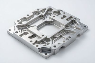
EV Battery Liquid-Cooling Connectors: Seal Face Precision & Torque (2026)
A liquid-cooled battery pack rarely fails at the chiller or the pump. It fails at a joint the size of a coin. A battery liquid-cooling connector that weeps a few millilitres after fifty thermal cycles is not just a quality nuisance — in a pack enclosure it is a path to insulation resistance loss, corrosion on busbars, and in the worst case a thermal event. Yet in 2026, most sourcing decisions on these connectors are still made on unit price and a generic 'mirror finish' note on a drawing, without ever asking what seal face precision or torque spec the joint actually needs to stay dry for the life of the vehicle.
This guide is written for the thermal engineer and the purchase lead who have to defend that decision. We break down what a battery liquid-cooling connector seal face really demands — roughness, flatness, form, and the clamping load that keeps it sealed — and we connect those requirements to the liquid-cooling coupler machining that can hold them repeatably. We compare turn-mill composite against split setups, show what tight tolerance CNC looks like at production volume, and lay out the pressure-test traceability a Tier 1 should be able to pull on demand.
The capability cited here is our own, not an industry average. LusterControl (Dongguan Licun Technology Co., Ltd.) was founded in 2015 and has spent 15 years in CNC precision machining with a focus on stainless-steel mirror finishing. We run 60 CNC machines in a 4,000 m² plant (2026 expansion; the former 2,000 m² figure is obsolete), hold ±0.005 mm in production, ship up to 500,000 parts per month, and operate under ISO 9001 certification with an ISO 13485 quality system established (certification advancing) and an IATF 16949 application in progress.
Every number below is a sourcing decision you can verify with data. We compare methods, never competitors, and we will name the honest trade-offs where a cheaper route is perfectly adequate — because the right connector is the one that fits your pack, your coolant and your volume, not the one with the longest spec sheet.
Table of Contents
- 1. Why Battery Liquid-Cooling Connectors Decide Pack Safety in 2026
- 2. Liquid-Cooling Coupler Machining: What the Seal Face Really Demands
- 3. Battery Liquid-Cooling Connector Seal Face: Ra, Flatness and Torque Spec
- 4. Turn-Mill Composite vs Split Setups for Tight Tolerance CNC
- 5. Tight Tolerance CNC: Holding Seal Face Specs at Volume
- 6. CNC Precision Machining and Pressure-Test Traceability
- 7. Buyer's Checklist: Vetting a Battery Liquid-Cooling Connector Supplier
- 8. Common Mistakes in Battery Liquid-Cooling Connectors Sourcing
New Energy Vehicles (Battery Thermal Management) CNC precision component
Why Battery Liquid-Cooling Connectors Decide Pack Safety in 2026
The smallest joint in the cooling loop is the one an auditor will ask about first.
Electric-vehicle pack architecture has moved decisively toward liquid cooling. Cell-to-pack and structural-pack designs push heat through cold plates and cooling plates, and every plate needs an inlet and an outlet that can be connected on the line and serviced in the field. That job falls to battery liquid-cooling connectors. The connector is at once a fluidic joint, a mechanical locator and often a leak-detection point, and it has to stay sealed through vibration, pressure pulses and a temperature swing that can span a cold winter start to a fast-charge session.
The commercial asymmetry is what makes this a design decision rather than a bill-of-materials line. A coupler is a low-unit-cost component; a leak found after pack assembly can mean a drained loop, a removed pack, a re-test of the whole batch and a hold on shipments. In a safety-critical system the downstream cost of a weeping joint is measured against warranty exposure and brand trust, not against the price difference between a controlled seal face and a generic one. Choosing battery liquid-cooling connectors is choosing which failure mode you are willing to live with.
- Battery liquid-cooling connector
- A quick-disconnect or threaded fluid coupling that joins a pack's coolant circuit to a cold plate, manifold or external loop, using a machined seal interface to prevent leakage.
- Seal face
- The machined surface — cone, flat or O-ring land — against which the sealing element bears. Its roughness, flatness and form govern whether the joint closes a leak path.
- Torque spec
- The specified tightening moment applied to a threaded connector, chosen to generate enough preload to compress the seal without crushing it, stripping the thread or distorting the body.
- Pressure-hold test
- A documented test in which the assembled joint is pressurized to a stated level and held for a stated dwell while pressure decay is measured against an acceptance limit.
We have covered the underlying surface-terminology in our broader CNC precision machining technical guides; this article stays on the single decision in front of you — what precision the joint needs and how to source it repeatably.
A cooling loop does not leak because the pump is weak. It leaks because one machined surface was a little less flat than the drawing assumed.
New Energy Vehicles (Battery Thermal Management) CNC precision component
Liquid-Cooling Coupler Machining: What the Seal Face Really Demands
On the seal face, the machining is the seal. There is no soft part to forgive a bad surface.
The sealing interface is a precision feature, not a finish
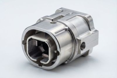
In most battery liquid-cooling connectors the barrier is formed where a machined cone or flat meets a mating seat, sometimes with an elastomer in the path and sometimes metal-to-metal. In either case the surface that touches the seal is a functional feature. Roughness that is too high leaves valleys for fluid to creep along; flatness that drifts across the face lets contact pressure concentrate on one side; a form error on a cone shifts the contact band off the seat. None of these show up in a visual inspection, and all of them show up in a pressure-decay test.
Three features do nearly all the work
- Roughness (Ra): the seal face is commonly specified at a low Ra; demanding liquid-cooling programs call for Ra ≤ 0.4 µm on the sealing surface, with the highest mirror grade we produce reaching 8K mirror Ra 0.2 µm.
- Flatness and form: the face must stay within a flatness band and, for cones, hold a matched angle so the contact band remains continuous around the circumference.
- Concentricity to the flow bore: the seal feature and the bore must share a datum frame, or the load applied by tightening will land unevenly and the joint will weep under a pressure cycle.
This is why liquid-cooling coupler machining is a setup-count problem before it is a cutting problem. A coupler body carries a seal face, a flow bore, a thread or locking feature and datum faces, all with a positional relationship to one another. Every time the part moves between fixtures, a datum shift is introduced. The result is a component that passes a dimensional check yet still weeps under pressure — because the relationship between the features, not any single dimension, was lost.
| Finish level | Ra target | Typical role in a battery liquid-cooling connector |
|---|---|---|
| Standard mirror | Ra ≤ 0.6 µm | General wetted surfaces and external appearance where sealing is not governed by this face |
| Demanding seal seat | Ra ≤ 0.4 µm | Seal seat and cone in higher-spec battery cooling programs |
| 8K mirror | Ra 0.2 µm | Highest mirror grade we produce, for the most demanding sealing faces |
| Non-sealing machined land | Per drawing, often coarser | Threads, flats and datum faces where finish does not govern leakage |
Ask a supplier not only what Ra they quote but where and how they measure it. A roughness value on a non-sealing face is easy to achieve and tells you nothing about the joint. More on how we select a process route by geometry is in the about our Dongguan plant.
Battery Liquid-Cooling Connector Seal Face: Ra, Flatness and Torque Spec
Both parameters look good on a spec sheet. Only one of them usually gets measured on the line.
Buyers often treat seal face finish and torque spec as separate topics. In practice they are one system: the torque creates the preload, and the preload presses two finished surfaces together. Get the finish right and the torque wrong, and you either fail to close the leak path or you crush the seal and distort the body. Get the torque right and the finish wrong, and you clamp a rough surface that still finds a path through. The table below gives the engineering trade-offs a specifier can defend, using target ranges to agree with your supplier rather than blanket guarantees.
| Factor | Controlled seal face & torque | Loosely specified alternative |
|---|---|---|
| Seal face roughness | Seat at Ra ≤ 0.4 µm; up to 8K mirror Ra 0.2 µm where required | 'Polished' with no measurement location or limit |
| Flatness / form | Defined flatness band; matched cone angle held in one setup | Visual acceptance, form unchecked |
| Concentricity to bore | Held within ±0.005 mm capability | Set by re-clamping between machines |
| Torque control | Specified moment with a documented tightening procedure | Torque by operator feel |
| Pressure-hold evidence | Pressure, dwell and acceptance limit recorded per batch | Visual dry check only |
| Field behaviour | Repeatable across thermal cycles and mate-unmate events | Weep risk rises after cycling |
| Unit cost | Higher machining and inspection content | Lower part cost, higher downstream risk |
- 1. Roughness. Name the Ra target, the exact face to be measured and the method. A number without a location is not a requirement.
- 2. Flatness and form. Specify the band and, for a cone, the angle. Ask how the supplier verifies form rather than just size.
- 3. Concentricity. Ask which single setup holds the seal face relative to the bore. If the answer involves three machines and an inspection guess, the quote hides a risk.
- 4. Torque. Specify the tightening moment and the tool used to apply it, and confirm whether the value is for a dry or lubricated seal.
- 5. Preload path. Confirm that the clamping load lands on the seal seat and not on a shoulder that can deform the body.
- 6. Coolant chemistry. Glycol concentration and additives affect elastomer swell and metal corrosion; state the fluid in the RFQ.
- 7. Evidence. Require a pressure-hold record with the test parameters, not a pass/fail stamp.
New Energy Vehicles (Battery Thermal Management) CNC precision component
Turn-Mill Composite vs Split Setups for Tight Tolerance CNC
The datum frame you set on day one is the leak performance you get on day one thousand.
For a rotationally symmetric coupler body, the cleanest way to protect the relationship between seal face, bore and thread is to machine them without moving the part. Turn-mill composite — turning and live-tool milling on one platform in one clamping — does exactly that. The blank is clamped once; the spindle turns the cone and sealing land, live tooling cuts flats and ports, and the bore is finished in the same coordinate system. For smaller connectors and manifold inserts, Swiss-type turning brings the same discipline to reduced diameters.
The alternative is a split route: turn on a lathe, mill on a second machine, drill on a third. It is not wrong — for a simple fitting with loose concentricity it is often the economical answer — but each handoff adds a datum transfer. When the seal face and the bore are cut in different fixtures, every part carries a small, variable offset. That offset is invisible on a caliper and obvious on a leak bench.
| Factor | Turn-mill composite, one setup | Split lathe → mill → drill |
|---|---|---|
| Bore-to-seal-face concentricity | Held by a single datum frame; ±0.005 mm capability | Limited by re-clamping and datum transfer |
| Cone angle consistency | Program-controlled, one tool reference | Depends on fixture repeatability between operations |
| Setup count | One primary clamping | Two to three handoffs |
| First-article repeatability | Program-driven, repeatable across shifts | Operator-dependent alignment |
| Best fit | Sealing couplers, manifold inserts, ported bodies | Simple fittings with loose concentricity |
Pros
- Choose turn-mill composite if your seal face must stay concentric to the bore across a production run.
- Choose it when a cone angle and a ported body have to agree in one datum frame.
- Choose it when first-article repeatability matters more than a few cents of cycle time.
Cons
- Choose a split setup if the fitting has no critical seal-to-bore relationship.
- Choose it if volumes are low and a dedicated turn-mill cell cannot be justified.
- Choose it if your drawing tolerances are loose enough that datum transfer is immaterial.
On our floor these cells sit alongside 5-axis capability and Swiss-type machines, so the route is chosen by geometry rather than by what a single machine can reach. That flexibility is part of what a drawing review is for.
Tight Tolerance CNC: Holding Seal Face Specs at Volume
A tolerance held on the first article is a promise. A tolerance held on the ten-thousandth is a process.
Tight tolerance CNC is often sold as a number — ±0.005 mm, ±0.01 mm — but the number is only meaningful when it is stable across a shift, across operators and across batches. Seal face work is especially unforgiving because the critical feature is usually a small area on a larger body. Tool wear, thermal drift and clamping force all move that face more than they move a general dimension, so the process has to be controlled, not merely inspected at the end.
What a controlled process looks like
A controlled route starts with a stable datum, keeps the part in one setup where possible, uses tool-life management so a finishing pass is not taken with a worn insert, and checks the critical feature at defined intervals. On the seal face specifically, that means measuring roughness on the actual sealing land and confirming form, not just diameter. Incoming bar stock is traceable by batch, and the machined parts carry that traceability forward.
| Capability check | What to ask | What a weak answer sounds like |
|---|---|---|
| Held tolerance | Is ±0.005 mm held in production or only on samples? | 'We can hit it on the first piece.' |
| Critical feature control | Is the seal face checked at defined intervals? | 'We inspect the outside diameter.' |
| Tool-life management | When is the finishing tool changed? | 'When the operator sees a problem.' |
| Batch traceability | Can a batch be traced to incoming material? | 'We don't normally keep that.' |
| Repeatability | What is the first-article pass rate across shifts? | 'It depends on who is running it.' |
- Tight tolerance CNC
- Computer-numerical-control machining held to a narrow dimensional band — in our production, ±0.005 mm — verified at the feature and sustained across a batch.
- Traceability
- The ability to link a finished part to its incoming material batch, process route, inspection records and test results.
- Datum frame
- The reference surfaces from which a part's features are dimensioned; keeping features in one datum frame avoids accumulated setup error.

New Energy Vehicles (Battery Thermal Management) CNC precision component
CNC Precision Machining and Pressure-Test Traceability
A pass/fail stamp is not evidence. The parameters behind it are.
For battery liquid-cooling connectors, the test that matters is the one that mimics service: pressurize the joint, hold it, and watch for decay. But a pressure-hold result is only useful if the buyer can see the conditions. A joint that holds at room temperature may weep after a thermal cycle; a leak rate accepted for water may be meaningless for a glycol mix. CNC precision machining produces the geometry, and the test record is what proves the geometry worked — so both belong in the supplier conversation.
The traceability chain a Tier 1 should be able to pull
- Step 1 — Incoming material: the batch of stainless bar or rod is identified and traceable.
- Step 2 — Process route: the part is machined on a defined route with the critical features held in one datum frame.
- Step 3 — Critical-feature inspection: seal face roughness and form are checked on the sealing land at defined intervals.
- Step 4 — Assembly: the seal is fitted and the connector tightened to the specified torque with a controlled tool.
- Step 5 — Pressure-hold test: the joint is pressurized to an agreed level, held for an agreed dwell, and decay is measured against an acceptance limit.
- Step 6 — Record release: the test parameters and result are retained against the batch, so a field question can be traced back to a run.
| Record | Minimum content | Why the buyer needs it |
|---|---|---|
| Material batch ID | Heat / lot, grade, supplier | Links a field issue to incoming stock |
| Inspection report | Seal face Ra, form, tolerance results | Proves the feature was controlled, not just the size |
| Torque record | Specified moment and tool calibration | Confirms the preload applied at assembly |
| Pressure-hold record | Pressure, dwell, temperature, acceptance limit, result | Turns a 'passed' claim into verifiable evidence |
This is where an established quality system shows its value. Passing a single test is easy; retaining the evidence across every batch is a discipline. We apply the same passivation discipline to stainless wetted parts, referencing ASTM A967 for chemical passivation in our documentation, then clean, flush and cap parts destined for a sealed loop.
Buyer's Checklist: Vetting a Battery Liquid-Cooling Connector Supplier
Five questions separate a supplier who controls the joint from one who only ships the part.
The difference between a quote that looks right and a connector that stays dry is almost always in the process behind it. Before you release a purchase order, ask for the following. A capable supplier will answer with documents; a weak one will answer with assurances.
- The drawing with the seal face called out: Ra target, measurement location, flatness and cone angle if applicable.
- A first-article inspection report that measures the critical feature — not just the easy outside dimensions.
- A sample pressure-hold record showing pressure, dwell, temperature and the acceptance limit.
- Confirmation of the machining route: which single setup holds the seal face relative to the bore.
- The quality-system evidence: certification status, batch traceability and the calibration record for the torque tool.
Those five items map directly onto the risks that cause field leaks — uncontrolled surface, uncontrolled form, uncontrolled preload and missing evidence. If a supplier stalls on any of them, that is useful information before a launch rather than after.
- Red flag: a 'mirror finish' with no Ra value or measurement location.
- Red flag: a leak claim with no stated test method or acceptance limit.
- Red flag: a connector body machined across several fixtures with no datum-control plan.
- Red flag: willingness to quote volume without a first-article inspection route.
You can see how we approach process selection and inspection across other demanding programs in our technical guides, and reach our team directly through the inquiry page for a drawing-specific answer.
New Energy Vehicles (Battery Thermal Management) CNC precision component
Common Mistakes in Battery Liquid-Cooling Connectors Sourcing
Most field leaks are decided at the RFQ stage, long before the first part is machined.
Having reviewed what a reliable joint requires, it is worth naming the mistakes that quietly undo it. These are not exotic errors; they are the shortcuts that look reasonable on a cost-reduction meeting slide and then surface as warranty claims two winters later.
- 1. Specifying a finish without a location. 'Mirror polish' on a general note does not control the face that seals. Name the face and the Ra.
- 2. Ignoring form. Roughness is easy to quote and flatness is easy to skip — but a face that is not flat will not seal at any Ra.
- 3. Leaving torque to feel. Without a specified moment and a controlled tool, preload varies from unit to unit and with it the leak performance.
- 4. Splitting the critical features across setups. Re-clamping between machines introduces datum error exactly where the joint is least tolerant of it.
- 5. Treating the pressure test as a formality. A pass/fail stamp without parameters cannot be compared across batches or defended to an auditor.
- 6. Ignoring the coolant. Glycol mix, additives and temperature change the seal's behaviour; state the fluid and the cycle in the RFQ.
- 7. Choosing on unit price alone. The part is cheap; the drained pack, the re-test and the held shipment are not.
The cost of a controlled seal face is measured in cents per part. The cost of an uncontrolled one is measured in packs.
New Energy Vehicles (Battery Thermal Management) CNC precision component
New Energy Vehicles (Battery Thermal Management) CNC precision component
New Energy Vehicles (Battery Thermal Management) CNC precision component
New Energy Vehicles (Battery Thermal Management) CNC precision component
FAQ: battery liquid-cooling connectors & New Energy Vehicles (Battery Thermal Management) Buyer Questions
A: Name the exact sealing face and a Ra target rather than a generic 'mirror' note. Demanding battery cooling programs commonly call for Ra ≤ 0.4 µm on the seal seat; the highest mirror grade we produce is 8K mirror Ra 0.2 µm. The value must come with a measurement location and method, or it cannot be verified.
A: Because the seal face, flow bore and thread need a shared datum frame. Turn-mill composite cuts them in one clamping, so re-clamping error never enters the relationship that governs leakage. Split setups are fine for loose-tolerance fittings but add datum risk to a sealing coupler.
A: Yes, when it is a controlled process rather than a sampled result: a stable datum, one setup where possible, tool-life management and interval checks on the critical feature. We hold ±0.005 mm in production across 60 machines; the point is sustaining it across batches, not hitting it once.
A: Ask for the parameters, not just a pass stamp: the pressure level, dwell time, temperature and acceptance limit, plus the result retained against the batch. That is what makes the claim verifiable and comparable across suppliers and across runs.
A: The terms overlap. A cold-plate coupler is the connector at a cold plate; a battery liquid-cooling connector is the broader class joining any pack coolant circuit. The sealing requirements — face finish, flatness, torque and traceability — are the same in either case.
A: Look for an established, auditable quality system. LusterControl holds ISO 9001 certification, has an ISO 13485 quality system established with certification advancing, and has an IATF 16949 application in progress. Ask for current certificates and scope, and for the process evidence rather than a claim.
If you are specifying a battery liquid-cooling connector and want to know whether your seal face, torque spec and tolerance stack will hold at volume, send us your drawing for a free DFM review. Our engineers will flag the features that decide leakage before you commit to a production order.
Request a Free CNC Quote