Precision Gears: DIN Standards Buyers Should Specify
If you are sourcing precision gears, spline shafts or couplings for a transmission, actuator, robot joint or powertrain in 2026, the part that fails first is rarely the one with the worst drawing. It is the one where the tolerance grade was left open. A gear that looks perfect on a CAD screenshot can still howl at speed, wear out early, or bind in the housing because the buyer never told the shop which DIN gear standards to hold. Most procurement teams specify the module and the tooth count and stop there, then wonder why two 'identical' batches behave differently.
This article is written from the buyer's side of the table. We walk through what actually makes precision gears perform, which DIN gear standards you should name on the drawing, and how modern CNC gear machining produces accurate spline shafts, gear shafts and couplings in one setup. The examples come from real transmission-component production, not a textbook, because LusterControl machines gear shafts, spline shafts and couplings daily under ISO 9001 and ISO 13485 controls.
By the end you will have a practical checklist of the seven specs to put on every gear drawing, a comparison of CNC gear machining versus conventional hobbing, and a clear read on which DIN gear standards separate a gear that lasts from one that scrapes. You will also see where a supplier's real capability, not its marketing, earns your order.
Table of Contents
- 1. What Are Precision Gears and Why DIN Gear Standards Decide Fit
- 2. How CNC Gear Machining Produces Accurate Precision Gears
- 3. DIN Gear Standards Buyers Should Specify: A Comparison Table
- 4. Spline Shaft Machining to DIN 5480: Tolerances and Fit
- 5. Coupling Machining for Precision Transmission Systems
- 6. CNC Gear Machining vs Hobbing: Which to Choose in 2026
- 7. Precision Gears Buyer's Checklist: 7 Specs to Put on the Drawing
- 8. Common Mistakes When Specifying DIN Gear Standards (and How to Avoid Them)
- 9. Why LusterControl's CNC Gear Machining Fits Global Transmission Buyers
Precision Transmission AI part image
What Are Precision Gears and Why DIN Gear Standards Decide Fit
A gear only works if its teeth agree with the shaft that drives it.
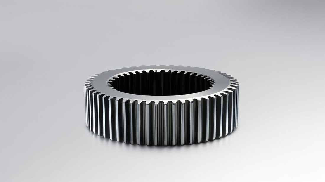
A precision gear is not a shape, it is a tolerance stack. The module sets the tooth size, the pitch diameter sets where the teeth sit, and the involute profile sets how load transfers from one tooth to the next. Change any one of those by a grade and the mesh changes from smooth to noisy. That is why leaving the standard off a drawing is the single most expensive shortcut a buyer can take: you pay for a 'gear' and receive a part whose accuracy nobody agreed to measure.
A gear is a tolerance stack, not a shape
Two gears with the same module and tooth count can behave like different components if one is cut to a tight DIN flank grade and the other to a coarse one. The coarse gear still meshes, but the contact pattern shifts, backlash grows, and at speed the noise and wear climb. When you name the DIN gear standards on the drawing, you are really naming the accuracy class the whole transmission depends on.
- Gear module
- The ratio of pitch diameter to tooth count; it sizes the tooth and must match across every meshing gear in the train.
- Involute profile
- The curved tooth shape that keeps contact ratio and load transfer smooth; DIN 867 defines the basic rack it is built from.
- Backlash
- The small clearance between meshing teeth; too little binds, too much makes the drive sloppy and noisy.
- Pitch diameter
- The reference circle where teeth effectively roll; its accuracy decides whether the gear actually runs true.
Why the standard matters more than the drawing
A drawing with a tooth count but no DIN reference leaves the tolerance grade to the shop's default, which is usually the cheapest grade it can defend. Naming DIN 3961/3962 grades on the drawing forces the conversation onto accuracy, not just shape. LusterControl's transmission work is built on this discipline: gear shafts, spline shafts and couplings are machined to the customer's specified DIN grade, then verified, so the 4,000th part matches the first. You can review our production scale on the company profile page.
Precision Transmission AI part image
How CNC Gear Machining Produces Accurate Precision Gears
Five-axis and turn-mill cells turn a shaft-and-gear into one controlled part.
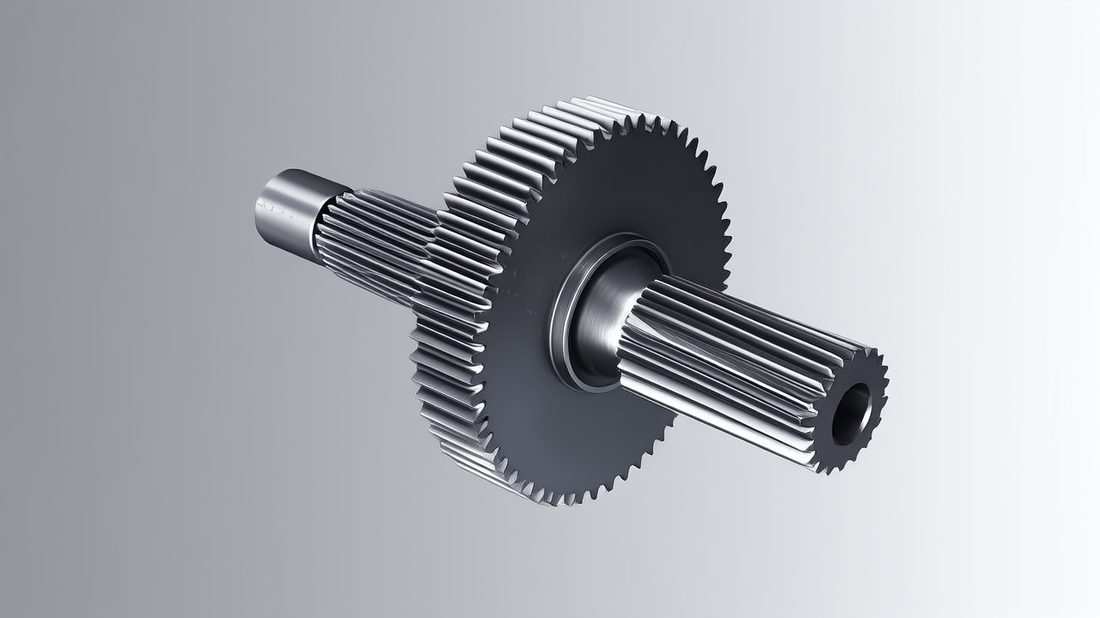
CNC gear machining covers more than cutting teeth. On 5-axis and turn-mill compound centers it produces the whole transmission component - the gear shaft, the spline shaft section, the coupling journal and the bearing seats - in coordinated operations that all reference the same datum. For many precision gears the teeth are cut soft, in the same setup as the shaft, so the tooth-to-bore relationship is locked by the machine instead of by a re-fixture you hope the inspector catches.
One setup for gear shafts and spline shafts
A gear shaft is fundamentally a turned part with teeth and features around it. On separate lathe and gear-cutting stations you turn, move, cut, move, re-turn, and trust every datum lines up. Each move is a chance to lose the ±0.005 mm between the bore and the tooth pitch circle. CNC gear machining on a turn-mill compound center does the turned shaft and the cut teeth in one chuck, so that relationship is held by the machine, not by re-measurement.
When to cut teeth on CNC vs a dedicated hobber
Dedicated hobbing is fast for huge runs of one identical gear. But it is poor at the parts transmission buyers actually struggle with: a shaft that is half gear, half spline, half coupling, with features only a 5-axis cell can reach. That is the gap CNC gear machining fills, and it is why LusterControl runs gear-shaft programs where the teeth, the DIN 5480 spline and the coupling bore are all cut and finished in one flow. See how our 5-axis capability maps onto real programs in this 5-axis and turn-mill capability article.
| Factor | Dedicated hobbing | CNC gear machining |
|---|---|---|
| Best lot size | Very high volume, one gear | Prototype to medium volume, mixed parts |
| Shaft + gear integration | Gear only, separate shaft op | Shaft, spline, coupling in one flow |
| Datum control | Re-fixtured, drift risk | Single setup, locked relationship |
| Flexibility | Low, tooled to one gear | High, same cell many geometries |
| Best for | Commodity spur gears | Precision gears on integrated shafts |
DIN Gear Standards Buyers Should Specify: A Comparison Table
Name the right DIN number and the shop knows exactly what to control.
The DIN gear standards family splits the job cleanly: one standard defines the tooth shape, others define how accurately that shape must be made, and one rates how much load the gear can carry. As a buyer, you do not need to memorize every clause, but you do need to name the ones that control fit and accuracy on your drawing. Leaving them off is how two shops quote the 'same gear' at two different accuracy classes.
| DIN standard | What it controls | When you should specify it |
|---|---|---|
| DIN 5480 | Involute splined connections - dimensions, fit and inspection of spline shafts | Any spline shaft or splined coupling hub |
| DIN 867 | Basic rack tooth profile for involute cylindrical gears | Every involute gear blank as the profile basis |
| DIN 3960 | Parameters and definitions for gear geometry | As the reference block on the drawing |
| DIN 3961 | Tolerances for tooth flanks (pitch, profile, runout grades) | Precision gears where noise and life matter |
| DIN 3962 | Tolerances for tooth thickness and backlash | Gears with a defined fit requirement |
| DIN 3965 | Tolerances for radial runout of teeth | High-speed precision gears and rotors |
| DIN 3990 | Calculation of load capacity (rating, safety factor) | Sizing and qualification of the gear train |
What each line actually buys you
DIN 867 plus DIN 3960 sets the language: the shop and the buyer agree on what a 'gear' means. DIN 3961 through DIN 3965 are where accuracy lives - flank grade, tooth thickness, and runout. DIN 3990 is the engineering math that says whether the gear will survive the load. For most precision gears in transmission and automation, naming DIN 3961/3962 grades plus the relevant DIN 5480 fit is the difference between a qualified part and a guess. LusterControl machines to the customer's named DIN gear standards and returns the inspection data to match.
Precision Transmission AI part image
Spline Shaft Machining to DIN 5480: Tolerances and Fit
A spline shaft is a gear you slide another part onto.
A spline shaft carries torque through an array of involute teeth cut along its length, and DIN 5480 is the standard that defines those involute splined connections - the major and minor diameters, the flank fit, and how the joint is inspected. The buyer's job is to specify the DIN 5480 fit class, because the same spline can be cut loose enough to slide by hand or tight enough to transmit high torque without play. Spline shaft machining lives or dies on that choice.
Fit classes and what they mean for your assembly
DIN 5480 defines fit combinations from sliding to press-type engagement. A sliding fit lets the hub move axially for a clutch or telescoping shaft; a tighter fit transmits torque with minimal backlash but needs controlled assembly force. Get the class wrong and either the hub won't slide or the joint rattles. On a turn-mill compound center, LusterControl cuts the spline and the shaft journal in one setup so the spline runs true to the bearing seats instead of chasing them across re-fixtures.
| DIN 5480 fit | Typical use | What the buyer controls |
|---|---|---|
| Sliding / loose | Telescoping shafts, clutches | Axial movement, easy assembly |
| Close sliding | Manual slide couplings | Low backlash, still adjustable |
| Tight / press | High-torque fixed joints | Max torque transfer, fixed assembly |
| Centering flank | Precision positioning | Which flank carries the locate load |
Coupling Machining for Precision Transmission Systems
A coupling is where two shafts agree to turn as one.
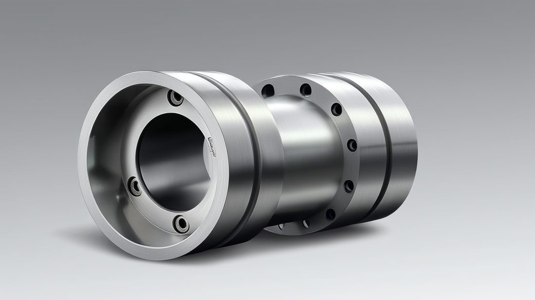
Coupling machining is the quiet half of transmission work. A coupling connects two shafts and must hold them concentric, balanced and true under load. The bore, the keyway or spline, and the flange faces all have to be cut to a relationship tight enough that the coupling does not introduce runout into the system. Coupling machining to a named DIN reference, plus careful boring and balancing, is what keeps a driveline quiet.
The boring and balancing that make a coupling true
Most coupling failures trace back to a bore that is slightly oversize or a keyway that is slightly off-axis, so the coupling sits at a small angle on the shaft. On a turn-mill cell the bore and the flange features are cut in one datum, and the result is a coupling that runs true to the shaft it mounts on. For higher-speed systems, balancing is the extra step that removes the residual eccentricity a tight tolerance alone cannot.
| Coupling type | Machining focus | Typical DIN reference |
|---|---|---|
| Rigid flange coupling | Bore trueness, bolt-circle accuracy | DIN fit on bore + face |
| Spline coupling | DIN 5480 spline + hub bore | DIN 5480 fit class |
| Oldham / disc coupling | Concentric bores, thin-web rigidity | DIN tolerances on both bores |
| Jaw coupling | Pilot diameter, keyway alignment | DIN fit on pilot + keyway |
Precision Transmission AI part image
CNC Gear Machining vs Hobbing: Which to Choose in 2026
The right method depends on volume, geometry and how much proof you need.
Buyers often ask whether CNC gear machining can match a dedicated hobber. The honest answer is that they are different tools for different jobs. Hobbing wins on raw throughput for one gear made by the million. CNC gear machining wins on integrated, lower-volume, mixed-geometry parts where the teeth are only one feature on a shaft that also needs a spline, a coupling bore and bearing seats. For most transmission buyers outside pure commodity scale, CNC gear machining is the more controllable path.
Choose CNC gear machining if
- Your gear is integrated with a shaft, spline or coupling, not a standalone blank
- Volume is prototype-to-medium, not millions of one identical gear
- You need the tooth-to-bore relationship held in one setup
- You want CMM reports and batch traceability for an audit trail
- The program will evolve and the same cell must flex to new geometries
Choose hobbing only if
- You need very high volume of a single, simple spur or helical gear
- The gear is a standalone blank with no integrated features
- Tolerance grade is open and there is no audit requirement
- Lead time and cost are driven purely by unit price at scale
| Requirement | CNC gear machining | Conventional hobbing |
|---|---|---|
| Integrated shaft + gear | Native in one setup | Needs separate operations |
| Tolerance proof | CMM + batch records | Often best-case only |
| Volume sweet spot | Prototype to medium | Very high volume |
| Flexibility | High across geometries | Low, tooled to one gear |
| Best for | Precision gears on real assemblies | Commodity gear blanks |
Precision Gears Buyer's Checklist: 7 Specs to Put on the Drawing
The quote you get is only as good as the package you send.
Before you release an RFQ for precision gears, spline shafts or couplings, assemble these seven items. They are what separate a real number from a guess, and they let a shop like LusterControl return a capable, on-time quote instead of a padded one. The same checklist works whether the part is steel, stainless or an aluminium transmission component.
- Module, tooth count and hand (for helicals) - the geometry the whole train depends on
- Named DIN gear standards: DIN 867/3960 basis plus DIN 3961/3962 grades
- DIN 5480 fit class for any spline shaft, with the centering flank specified
- Material grade and any heat-treat or ASTM A967 cleanliness requirement
- Tolerance only on functional surfaces, with GD&T on bore, pitch and runout
- Required surface finish (Ra target) on fit surfaces and tooth flanks
- Volume, phasing and quality paperwork expected: CMM report, first-article, batch traceability
When your package is complete, a supplier can run a free DFM review and flag a spline that fights the material, a bore that needs opening, or a tolerance that should be relaxed. That conversation before cutting saves more than any negotiation after the parts are boxed. Start one on our inquiry page.
Precision Transmission AI part image
Common Mistakes When Specifying DIN Gear Standards (and How to Avoid Them)
Most gear problems are specified, not machined.
After reviewing many transmission RFQs, the same avoidable errors show up again and again. None of them are the machinist's fault; they are written into the drawing before the first chip is cut. Fixing them at the spec stage is free compared with reworking a lot.
Pros
- Naming DIN 3961/3962 grades so accuracy is measurable, not assumed
- Marking the DIN 5480 centering flank so the spline locates correctly
- Tolerancing only functional surfaces to control cost
- Requesting batch traceability for audit-ready transmission parts
Cons
- Specifying only module and tooth count, leaving grade open
- Assuming 'gear' implies a tight tolerance the shop never agreed to
- Over-tolerancing every dimension and inflating cost for no benefit
- Forgetting material cert and heat-treat notes until after first article
The grade gap that bites at speed
The most expensive mistake is the silent one: a drawing that says 'precision gear' with no DIN grade. The shop delivers a perfectly good coarse-grade gear, the buyer fits it, and at 3,000 rpm the train whines and wears. The fix costs nothing on paper - write the DIN 3961 grade on the drawing - but it changes everything on the test bench. For the highest DIN grades on hardened, ground gears, confirm the heat-treat and finish-grind step with your supplier up front; CNC gear machining handles the soft cut and tight turned features, and a qualified grind step closes the last microns.
Why LusterControl's CNC Gear Machining Fits Global Transmission Buyers
Transmission discipline sharpens the whole floor.
We did not add spline shaft and coupling machining to chase a badge. We added them because the same discipline precision gears demand - rigid cells, ±0.005 mm control, single-setup datum locking and batch traceability - is exactly what makes every other industry's parts better. A transmission program is a stress test that lifts the whole process, which is why LusterControl serves transmission alongside medical, automotive, semiconductor, UAV and robotics work.
The quality system underneath the metal
Every gear shaft, spline shaft and coupling at LusterControl is made under ISO 9001 and ISO 13485 controls, with IATF 16949 in progress, and with passivation where ASTM A967 cleanliness is required. For buyers that means the paperwork trail is built in, not bolted on after the fact. You get material certs, CMM data and batch records that survive an audit, whether the part is a one-off prototype or a 500K-piece run.
One house from drawing to volume
LusterControl has supplied precision components to brands such as De'Longhi, Donlim and Breville, and supports industries from medical and automotive to UAV, robotics and precision transmission. That breadth means the turn-mill cell cutting your spline shaft also runs parts held to medical and automotive discipline, so the cross-pollination leaves your precision gears production-ready. Our drone-lightweighting work shows the same logic in action, covered in this 5-axis CNC machining article.
Precision Transmission AI part image
Precision Transmission AI part image
Precision Transmission AI part image
Precision Transmission AI part image
FAQ: precision gears & Precision Transmission Buyer Questions
A: Start with DIN 867 and DIN 3960 as the geometry basis, then name DIN 3961/3962 grades for tooth flank and thickness accuracy, DIN 3965 for runout on high-speed gears, and DIN 3990 for load rating. For any splined connection, add the DIN 5480 fit class. Naming the grades is what makes accuracy measurable instead of assumed.
A: Our turn-mill and 5-axis cells hold ±0.005 mm repeatably on turned features such as bores, journals and pilot diameters, with Ra 0.2 um (8K mirror) achievable on fit surfaces. Teeth are cut via CNC gear machining to the customer's specified DIN grade and verified per lot with CMM reports and first-article inspection.
A: Choose CNC gear machining when the gear is integrated with a shaft, spline or coupling, when volume is prototype-to-medium, or when you need the tooth-to-bore relationship held in one setup with batch traceability. Choose hobbing only for very high volume of a single, simple standalone gear where unit price at scale dominates.
A: Yes. Spline shaft machining to DIN 5480 is done on our turn-mill compound and 5-axis centers, with the involute spline, the centering flank and the shaft journal cut in one datum so the spline runs true to the bearing seats. Fit class and inspection follow the customer's specified DIN 5480 requirement.
A: Every lot carries material certification, in-process records and inspection data tied to the batch. Combined with ISO 9001 and ISO 13485 discipline, this gives transmission buyers an audit-ready trail from raw bar to finished gear shaft, spline shaft or coupling.
A: Send the module, tooth count and hand, the named DIN gear standards with grades, the DIN 5480 fit class for splines, the material grade and any heat-treat or ASTM A967 need, tolerance only on functional surfaces, the required Ra, and your volume phasing with the quality paperwork expected. A complete package enables a free DFM review and a real number.
Send us your gear, spline shaft or coupling drawing for a free DFM review and a realistic lead-time quote, whether it is a prototype or a production run.
Request a Free CNC Quote