Invar Machining for Optical Components: 2026 Stability Guide
If you design or buy optical assemblies, you already know the uncomfortable truth: the lens is only as stable as the part holding it. A mirror base that expands a few microns across a normal lab temperature swing quietly walks your focus, your beam alignment, or your inspection repeatability. The symptom shows up as 'it was fine yesterday' — and yesterday was 6 degrees cooler.
That is why a growing number of optical makers now specify Invar bases instead of aluminium or stainless. Invar is a low-coefficient-of-thermal-expansion (low-CTE) alloy that barely moves with temperature, so the optical components mounted on it stay put. In this 2026 guide we explain what invar machining actually involves, how a CNC instrumentation shop holds sub-micron stability on a gummy, work-hardening alloy, and exactly what to request from a supplier before you release a purchase order.
We write this from the buyer's side. You will get a material comparison with real CTE numbers, a process walk-through, a decision table for when Invar is worth the cost, a seven-item sourcing checklist, and the common mistakes that turn a stable design into a scrap batch. Where we cite our own plant, the numbers are verifiable: 60+ CNC machines, a 4,000 m2 Dongguan source factory, 500,000 parts per month, ISO 9001 / ISO 13485, and IATF 16949 in progress.
Table of Contents
- 1. Why Optical Components Drift When the Base Moves
- 2. Sub-Micron Stability Starts With the Base Material
- 3. Invar Machining: The Process Behind a Stable Mirror Base
- 4. Lens Barrel Machining vs Invar Base Machining: What Changes
- 5. How CNC Instrumentation Holds +-0.005 mm on Invar
- 6. Optical Components That Need Invar Bases: Choose A or Choose B
- 7. Sub-Micron Stability in Production: The Buyer's Checklist
- 8. Common Mistakes When Sourcing Invar Machining for Optics
- 9. CNC Instrumentation at a Dongguan Source Factory: Why LusterControl
Optical AI part image
Why Optical Components Drift When the Base Moves
Thermal expansion is the silent failure mode most optical buyers discover after first article, not before.
Every material grows when it warms and shrinks when it cools. For a structural bracket that movement is invisible. For an optical component it is fatal, because the tolerances that matter are measured in microns. A 100 mm aluminium base that rises 10 degrees Celsius grows roughly 23 microns; the same base in Invar grows about 1.3 microns. If your spec allows a 2-micron focus window, aluminium has already failed and Invar has not started.
- Coefficient of thermal expansion (CTE)
- How much a material's length changes per degree of temperature, usually x10^-6 per K near room temperature. Lower CTE means less drift.
- Optical component drift
- The change in focus, beam path or alignment caused by dimensional movement of the structure holding the optic.
- Low-CTE alloy
- A material formulated to minimise thermal growth; Invar (roughly 36% nickel iron) is the classic example.
The buyer's mistake is treating drift as a 'nice to have' note buried in the drawing. It is the spec. When an optics maker tells us they need a stable mirror base, the first question we ask is not 'what shape' but 'what temperature range and what allowable focus shift'. That single answer decides the material, the process, and the metrology, long before the first chip is cut.
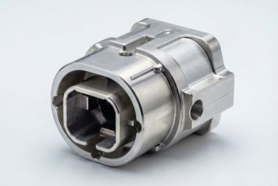
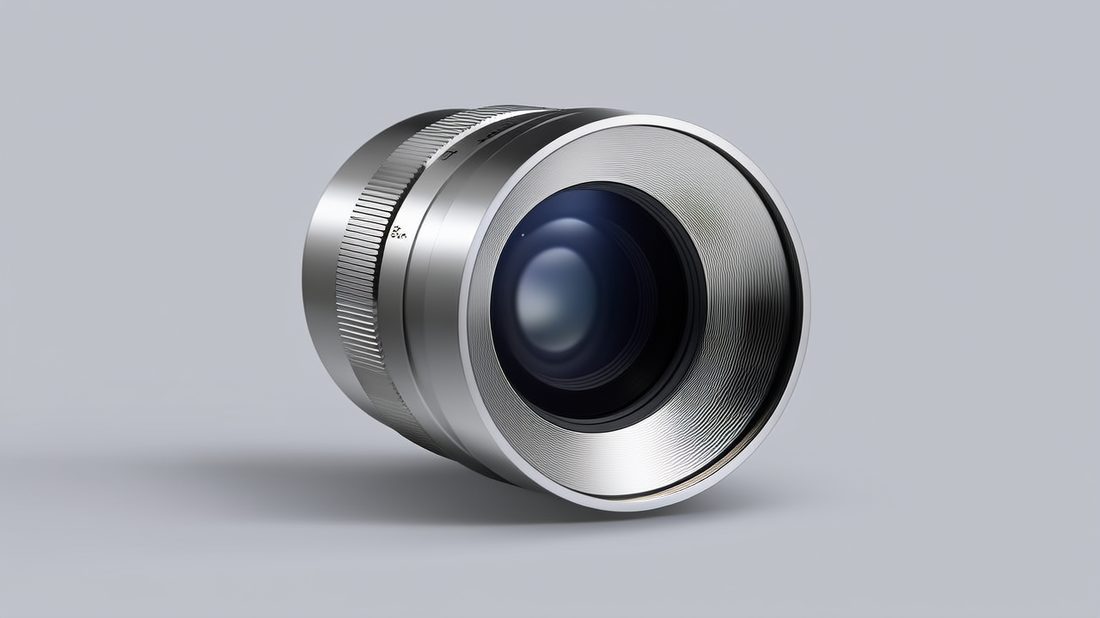
This is the same discipline behind our optical lens barrel work, where bore concentricity and relationship tolerances are held so the optic seats correctly the first time. A barrel and a base are different parts, but the enemy is the same: movement you did not budget for.
Optical AI part image
Sub-Micron Stability Starts With the Base Material
Before any machining discussion, the material choice sets the ceiling on how stable your assembly can ever be.
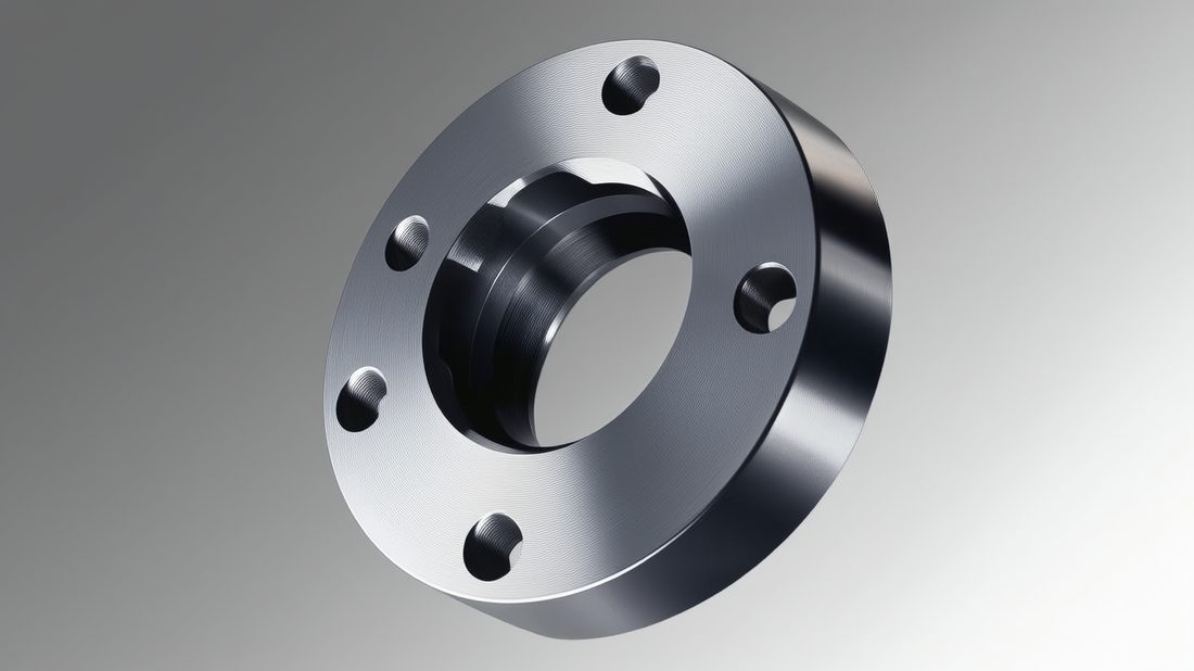
Sub-micron stability is not a finish you add at the end. It is a property built into the base material. Aluminium is light and cheap but moves a lot; stainless is stiffer and more corrosion resistant but still expands roughly 13 times more than Invar over the same temperature change; Invar trades mass and cost for near-frozen dimensions. The table below is the one we show procurement when they ask 'do we really need Invar'.
| Property | Aluminium 6061 | Stainless 304 | Invar (Fe-36Ni) | Why it matters to you |
|---|---|---|---|---|
| CTE near 20 C (x10^-6/K) | 23 | 17 | 1.3 | Invar moves ~15x less than aluminium under the same swing |
| Typical optics use | Lightweight frames | Housings, fixtures | Mirror / base plates | Pick Invar when focus shift is the failure mode |
| Machining behaviour | Easy, gummy chips | Work-hardens | Gummy, work-hardens | Drives cycle time and tool wear (see process section) |
| Mass per part | Low | Medium | High | Balance stability against your weight budget |
| Relative material cost | Low | Medium | Higher | Justify only where drift is the actual spec |
Reading that table for your own part: if drift is tolerated by design (a consumer camera with software stabilisation), aluminium is the rational choice and nobody should pay for Invar. If drift is the failure mode (a laser module, a microscope stage, a medical imaging optic), Invar or another low-CTE alloy is the cheapest way to buy stability without active thermal control.
- Choose Invar if your allowable focus or alignment shift is in the low-micron range and the environment swings more than a few degrees.
- Choose stainless if you need corrosion resistance and stiffness but can tolerate its larger CTE with design margin.
- Choose aluminium if weight and cost dominate and the optic is stabilised or non-critical.
- Choose a low-CTE alloy only after you have written down the temperature range and the allowable movement in microns.
- Choose to spec the CTE requirement on the drawing, not just 'stable base', so the shop cannot substitute a cheaper material.
- Choose to fold the base material decision into the DFM review, because it changes how the part is fixtured and measured.
Invar Machining: The Process Behind a Stable Mirror Base
Invar is machinable, but it is gummy, work-hardens, and springs; the process has to respect all three.
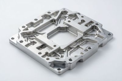
Invar machining is where a stable design meets reality. The alloy is ductile and tends to work-harden under the tool, which means a dull insert or a timid feed rate can smear the surface instead of cutting it and then harden the next layer. It also has low thermal conductivity, so heat stays in the cut. And it springs because of low stiffness relative to its mass. A shop that machines it like aluminium will hand you a part that looks right and measures wrong. Here is the sequence we use for a low-CTE mirror base.
Step 1: Material verification and stress relief
We confirm the mill cert and the actual CTE class, then stress-relieve if the blank carries residual mill stress. Skipping this step is the most common reason an Invar base moves after you bolt it down — the part relaxes on the bench, not in the oven. For buyers this is the difference between 'measured flat at the shop' and 'flat at your lab'.
Step 2: Rough and finish cut on 5-axis or turn-mill
We rough with sharp inserts and positive rake, then finish to +-0.005 mm in as few setups as possible. Five-axis and turn-mill compound centres let us reach features in one clamp, which protects the relationship between the mounting face and the optic seat. With Invar, every extra fixturing move is a chance to lose the flatness you are paying for.
Step 3: Light passivation where stainless variants are used
Pure Invar is not stainless, so many optical bases use a corrosion-resistant low-CTE variant or a stainless seat. Where the part is stainless, we can passivate to ASTM A967 so the surface resists corrosion in the field. This is a buyer-facing spec medical and fluid programs actually audit, and it costs nothing if it is part of the same controlled sequence.
Step 4: Metrology and documentation
We measure flatness and the seat-to-face relationship on a CMM and hand back the numbers, not a photograph. For an optics buyer the documented value is the deliverable; a shiny surface with no measurement is just a paperweight with hopes. Our earlier write-up on 8K mirror finishing at Ra 0.2 um covers the profilometer discipline that applies to any precision face.
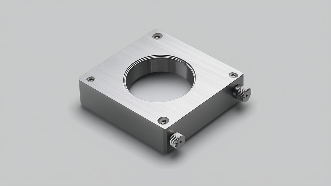
Optical AI part image
Lens Barrel Machining vs Invar Base Machining: What Changes
They share a tolerance language but solve opposite problems, and mixing up the two is an expensive error.
Lens barrel machining and Invar base machining both live in the precision world, but they optimise for different failures. A barrel protects bore concentricity and thread fit so the optic seats true; a base protects flatness and low CTE so the optic stays put. If you brief a supplier as if they are the same part, you will get the wrong process and the wrong inspection.
| Factor | Lens Barrel Machining | Invar Base Machining |
|---|---|---|
| Dominant requirement | Bore concentricity, thread fit | Flatness, low CTE, rigidity |
| Typical tolerance | +-0.005 mm on bore | +-0.005 mm on seats plus flatness |
| Common material | Aluminium, stainless, brass | Invar / low-CTE alloy |
| Key risk if wrong | Binding or tilted optic | Focus drift with temperature |
| Finish need | Ra <=0.6 um typical | Ra <=0.6 um, sometimes mirror |
| Process emphasis | Turn-mill, 5-axis | 5-axis, stress relief, metrology |
The practical takeaway for a buyer: when you request a quote, name the dominant requirement first. If you say 'precision optical part' with no detail, the shop will optimise for whatever they machine most often. Tell them 'I need a low-CTE base held to +-0.005 mm with documented flatness' and you get a different, correct plan.
Pros
- Naming the dominant requirement gets you the right process on the first quote
- Separating barrel and base specs avoids over-paying for a tolerance you do not need
- Documented flatness speeds first-article approval for optics programs
Cons
- Treating them as identical parts risks the wrong inspection plan
- Over-specifying either one inflates cost with no function gain
- Assuming the shop infers 'optical' from the shape usually ends in rework
How CNC Instrumentation Holds +-0.005 mm on Invar
Stability is not luck; it is machines, fixtures and measurement working inside a documented system.
CNC instrumentation is the unglamorous backbone of every stable optical base. Holding +-0.005 mm on a work-hardening, low-stiffness alloy is not about one magic machine; it is about controlling the whole chain: rigid fixturing, sharp tooling, thermal-stable measurement, and lot-level traceability. When an optics buyer asks 'can you hold the tolerance', the honest answer is a tour of the system, not a number on a brochure.
| Capability | LusterControl spec | What it buys you |
|---|---|---|
| Dimensional tolerance | +-0.005 mm | Seats and faces hold across the batch |
| Mirror finish | Ra <=0.6 um std, Ra 0.2 um (8K) max | Clean, low-loss optical surfaces |
| Plant and machines | 4,000 m2, 60+ CNC (5-axis, turn-mill, Swiss-type) | Volume without dropping the bar |
| Monthly capacity | 500,000 parts | Prototype-to-production scale |
| Quality system | ISO 9001, ISO 13485 done, IATF 16949 in progress | Audit-ready traceability |
| Passivation | ASTM A967 available | Corrosion resistance on stainless |
For low-CTE bases the two capabilities that decide success are relationship metrology and traceability. Relationship metrology means we measure how the optic seat relates to the mounting face, not just each feature in isolation. Traceability means every batch ties back to the source bar and mill cert, so if a base drifts in the field you can answer 'which heat, which machine, which inspector' in minutes. That is the evidence medical and instrumentation auditors want.
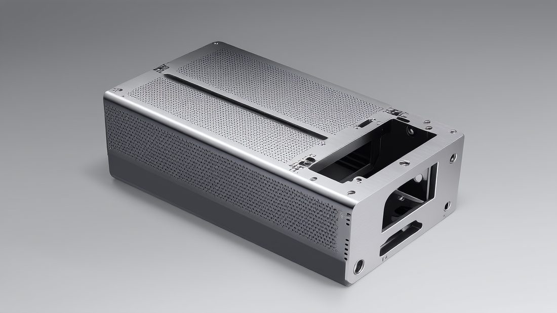
Optical AI part image
Optical Components That Need Invar Bases: Choose A or Choose B
Use this decision table to stop paying for Invar where aluminium would do, and stop risking drift where Invar is mandatory.
Most sourcing arguments over Invar are really arguments over whether drift is a failure mode. The table below maps common optical programs to the base material that fits, so you can defend the choice to procurement and to engineering at the same time.
| Your program | Recommended base | Why |
|---|---|---|
| Microscope / metrology stage | Invar or low-CTE | Focus must hold across lab temperature swings |
| Laser / fibre module | Invar base plate | Beam alignment drifts with any base movement |
| Consumer camera barrel | Aluminium + stabilised design | Cost wins; drift tolerated by design |
| Aerospace / satellite optic | Invar or invar-class | Thermal-vacuum swings are extreme |
| High-volume appliance optic | Aluminium, anodised | Price per unit dominates |
| Medical imaging optic | Invar or stabilised stainless | Repeatability is audited |
- Choose Invar if the spec is 'repeatable to low microns across a real temperature range' and field failure is not acceptable.
- Choose aluminium if the program is cost-driven and the optic is stabilised or non-critical.
- Choose stabilised stainless if you need corrosion resistance plus tighter drift control than aluminium allows.
- Choose to document the decision in the DFM record so a future engineer understands why Invar was (or was not) used.
Sub-Micron Stability in Production: The Buyer's Checklist
Seven items to request before you approve a low-CTE optical base order.
Sub-micron stability is easy to claim on a quote and hard to prove in a batch. Before you release the PO, ask the supplier for these seven items. If they cannot produce them, the low price is the warning, not the win.
- Ask for the material cert confirming the low-CTE class and the actual CTE range, not just 'Invar'.
- Ask for the stress-relief step in writing; residual stress is the top cause of post-machining drift.
- Ask for +-0.005 mm tolerance plus documented flatness on the seat-to-face relationship, as separate callouts.
- Ask for a first-article CMM report with the real numbers, not a photograph of a shiny part.
- Ask for ASTM A967 passivation where the base is stainless or a corrosion-resistant variant.
- Ask for lot-level traceability back to the source bar and mill cert.
- Ask for lead time at your real volume, not a one-off sample quote.
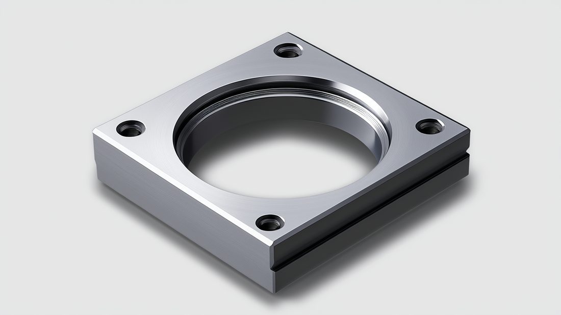
Optical AI part image
Common Mistakes When Sourcing Invar Machining for Optics
These five errors cost optics buyers the most money and the most credibility.
- Specifying 'stable base' with no CTE number, so the shop substitutes aluminium to win the price.
- Skipping stress relief to save a day, then watching the base relax and drift after it is bolted down.
- Assuming a shiny photo equals a stable base, when only a CMM report proves the flatness and relationship.
- Machining Invar like aluminium with dull inserts, which work-hardens the surface and locks in stress.
- Choosing the lowest price with no lot-level traceability, then failing a medical or instrumentation audit.
If you want the wider context on clean, stable machining for sensitive programs, our semiconductor ultra-clean machining guide covers the same discipline of documented process and traceability applied to vacuum hardware.
CNC Instrumentation at a Dongguan Source Factory: Why LusterControl
A buyer's view of what our plant actually brings to a low-CTE optical base program.
CNC instrumentation for optical bases is where a Dongguan source factory earns its place in a global supply chain. We are not the lowest-cost shop on aluminium, and we do not claim to be. We are the shop that holds +-0.005 mm on difficult alloys, documents every relationship dimension, and scales from a first article to 500,000 parts a month inside one quality system. For an optics buyer that combination is rarer than it should be.
We do not claim an optics-specific certification, and we will not pretend one exists. What we offer is verifiable: ISO 9001 and ISO 13485 completed, IATF 16949 in progress, real client programs such as De'Longhi, Donlim and Breville for precision 8K-mirror parts, and a UAV client whose first order reached RMB 1.2M. For your low-CTE base, that means a supplier who can prove the process and trace the batch, which is what stability actually requires.
Start on our inquiry page or read more on the about page and the blog for the full capability map.
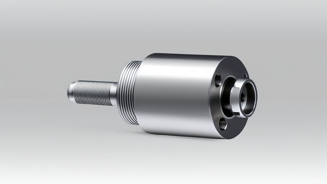
Optical AI part image
Optical AI part image
Optical AI part image
Optical AI part image
FAQ: optical components & Optical Buyer Questions
A: Because Invar has a coefficient of thermal expansion around 1.3 x10^-6/K, roughly 15 times lower than aluminium's 23 x10^-6/K. Over a normal temperature swing that difference is the gap between stable focus and a drifted optic. Makers choose Invar when focus or alignment shift is the actual failure mode.
A: Yes. Invar is gummy, work-hardens under the tool, has low thermal conductivity, and springs because of its low stiffness. It needs sharp positive-rake inserts, controlled feeds, often a stress-relief step, and relationship metrology. A shop that treats it like aluminium will deliver a part that measures wrong after it relaxes.
A: We hold +-0.005 mm on features and document flatness on the seat-to-face relationship with a CMM first-article report. Mirror faces can reach Ra 0.2 um (8K). Every batch carries lot-level traceability back to the source bar and mill cert under ISO 9001 / ISO 13485.
A: When drift is the failure mode: microscope and metrology stages, laser or fibre modules, aerospace or satellite optics, and audited medical imaging parts. For cost-driven consumer optics with software or design stabilisation, aluminium is the rational choice. The decision should always start from the temperature range and allowable movement in microns.
A: Ask for the low-CTE material cert with the actual CTE range, the stress-relief step in writing, +-0.005 mm plus documented flatness, a first-article CMM report, ASTM A967 passivation where stainless, lot-level traceability, and lead time at your real volume. If a supplier cannot show these, the low price is the warning.
A: We machine low-CTE and precision alloys for optical and instrumentation bases using 5-axis and turn-mill centres, with stress relief and relationship metrology. We hold ISO 9001 and ISO 13485 (IATF 16949 in progress) and do not claim an optics-specific cert; we prove the process and trace every batch instead. Send your drawing for a free DFM review to confirm the material and process fit.
Send us your drawing for a free DFM review and we will tell you the exact material, tolerance, process and lead time your low-CTE optical base needs before you commit to a purchase order.
Request a Free CNC Quote